Back to FS2004 SDK Overview

Microsoft Flight Simulator 2004:
A Century of Flight
Software Development Kit
Aircraft Container System
November 2003

Aircraft Container SDK Overview...............................................................................................................1
File hierarchy..................................................................................................................................................2
The aircraft.cfg file.........................................................................................................................................3
Introduction..................................................................................................................................................3
Testing Changes to aircraft.cfg....................................................................................................................3
Configuration sets and their [fltsim. ] sections...........................................................................................4
[General] section.........................................................................................................................................7
[forcefeedback] section................................................................................................................................8
[Reference_Speeds] section.......................................................................................................................10
[flight_tuning] section................................................................................................................................10
[weight_and_balance] section...................................................................................................................12
[fuel] section..............................................................................................................................................16
[GeneralEngineData] section...................................................................................................................16
[piston_engine] section..............................................................................................................................17
[propeller] section ...................................................................................................................................19
[TurbineEngineData] section...................................................................................................................21
[jet_engine] section ...................................................................................................................................22
[turboprop_engine] section......................................................................................................................22
[contact_points] section.............................................................................................................................22
[gear_warning_system] section ................................................................................................................25
[brakes] section..........................................................................................................................................26
[airplane_geometry] section .....................................................................................................................26
[flaps.n] section..........................................................................................................................................29
[electrical] section.....................................................................................................................................30
[pitot_static] section..................................................................................................................................33
[exits] section............................................................................................................................................34
[views] section...........................................................................................................................................34
[lights] section...........................................................................................................................................34
[keyboard] section.....................................................................................................................................35
[radios] section..........................................................................................................................................36
[smokesystem] section................................................................................................................................36
[effects] section..........................................................................................................................................36
[hydraulic_system] section .........................................................................................................37
[stall_warning] section .......................................................................................................38
i

[direction_indicators] section....................................................................................................................38
[attitude_indicators] section ...................................................................................................................38
[turn_indicators] section...........................................................................................................................38
[airspeed_indicators] section....................................................................................................................39
[autopilot] section......................................................................................................................................39
Helicopter specific sections..........................................................................................................................44
[helicopter] section....................................................................................................................................44
[fuselage_aerodynamics] section...............................................................................................................47
[MainRotor] section...................................................................................................................................47
[SecondaryRotor] section..........................................................................................................................48
The kneeboard content files.........................................................................................................................49
Creating or modifying the Checklist and Reference pages........................................................................50
The panel.cfg file...........................................................................................................................................50
The model.cfg file..........................................................................................................................................50
Introduction................................................................................................................................................50
[models] section.........................................................................................................................................50
The sound.cfg file..........................................................................................................................................51
Introduction................................................................................................................................................51
[fltsim] section..........................................................................................................................................51
[sound_engine] section..............................................................................................................................52
Specific engine sound sections (sound lists)..............................................................................................54
[wind_sound] section.................................................................................................................................56
Ground sound sections...............................................................................................................................58
Other sound sections..................................................................................................................................60
The Texture folder........................................................................................................................................62
Using aliasing................................................................................................................................................63
An example.................................................................................................................................................63
ii

Aircraft Container SDK Overview
The Aircraft Container system organizes Flight Simulator aircraft files and attributes so that most
aircraft-related files are located close together. This logical and consistent organization makes
the files easy to customize. This document includes the following sections:
• File hierarchy
Provides an overview of the aircraft container system’s organizational structure.
• The aircraft.cfg file
Explains the structure of and parameters in an aircraft’s aircraft.cfg file, including the use
of configuration sets that enable components to be shared among several aircraft.
• The kneeboard content files
Explains the structure of the files that populate the tabs of the kneeboard, and how to
customize them.
• The panel.cfg file
Provides a brief description of an aircraft’s panel.cfg file.
• The model.cfg file
Explains the structure of and parameters in an aircraft’s model.cfg file
• The sound.cfg file
Explains the structure of and parameters in an aircraft’s sound.cfg file
• The Texture folder
Describes the contents of an aircraft’s Texture folder.
• Using Aliasing
Explains how to use aliasing to avoid file duplication by sharing components among
several aircraft.
Important Notes:
• This SDK documents the aircraft container system and related files as implemented in
Flight Simulator 2004. Not all of the features and functionality described here are
backward-compatible with aircraft from earlier versions of Flight Simulator and Combat
Flight Simulator.
• This document contains information on how to modify and share components among
existing aircraft. It does not explain how to create new aircraft.
• The .cfg files referenced in this document are simple text files (“configuration” files with
a .cfg extension) and can be viewed and edited using any text editor, such as Microsoft
Notepad. They can be found in the appropriate aircraft subfolders of the FS9\Aircraft
folder. To become more familiar with the structure and syntax used in .cfg files, you
should view actual files as you read this document. These files should be modified only –
and with caution--by experienced developers, as changes could render aircraft
inoperable.
1

• The information included in this SDK is not supported by Microsoft Product Support.
File hierarchy
The aircraft container system organizes aircraft-related files and folders in a hierarchical and
consistent way and mirrors the way the files interact with one another. An aircraft “container” is
simply an aircraft folder within the FS9\Aircraft folder. Each aircraft folder (e.g., B737_400,
Lear45, C182) contains:
• aircraft.cfg Specifies which model, panel, sound, texture, and kneeboard components to
use, as well as certain aircraft-specific parameters.
• aircraftname.air Contains the aircraft’s flight model.
• aircraftname_check.htm Provides aircraft-specific text for the Checklists tab of the
kneeboard.
• aircraftname_ref.htm Provides aircraft-specific text for the Reference tab of the
kneeboard.
• Model folder Contains the model.cfg file that specifies the visual models to render
during normal flight and during a crash, as well as the visual model color scheme. Also
contains the .mdl visual model files.
• Panel folder Contains the panel.cfg file that defines the layout of an aircraft’s
instrument panels and view parameters. Also contains associated .bmp files. (For detailed
information about panels, see the Panels SDK.)
• Sound folder Contains the sound.cfg file that describes the aircraft’s sounds and the
initial, minimum, and maximum volume associated with each sound. Also contains
associated .wav files.
• Texture folder Contains textures (.bmp files) used in the presentation of the aircraft’s
visual model.
Note that through aliasing, more than one aircraft can access and use the same panel, model, and
sound .cfg files (and hence the same panel, model, and sound component files) without copying
the files to all the aircraft containers. For more information, see Using Aliasing later in this
document.
2

The aircraft.cfg file
Introduction
The aircraft.cfg file represents the highest level of organization within an aircraft container. Each
aircraft has its own aircraft.cfg file located in its container (aircraft folder). For example, the
Cessna 182S aircraft.cfg can be found at
drive:\..\FS9\Aircraft\C182\aircraft.cfg
The aircraft.cfg file specifies the versions of the aircraft included in the aircraft container, as well
as the attributes (name, color, sound, panels, gauges, and so on) for each aircraft and where to
find the files that define those attributes.
Within the aircraft.cfg file there are a number of sections. Brackets enclosing the section name
identify the various sections. In order for Flight Simulator to make proper use of any variable, it
is important that the variable be located in the correct section. While exact spelling is important,
none of the terms is case-sensitive.
Testing Changes to aircraft.cfg
To see the effects of a change, the aircraft must be reloaded. Aircraft are loaded into the memory
cache from disk, so you have to flush the cache to enable your changes to be reflected in-game.
This involves a couple steps:
1. Configure a key command to Reload User Aircraft . Set up a key command to reload
your aircraft from within the simulation. Go to Settings, Controls Assignments, and
scroll down to the “Reload User Aircraft” event. By default, it’s unassigned. Use
Change Assignment to configure a keystroke combination for this event. Once
assigned, you can use this key command to reload the aircraft within the simulation.
2. Turn off AI Traffic in the game . AI traffic aircraft are maintained in the cache and even if
you update the aircraft you’re currently piloting, if the same aircraft is being used by AI
traffic, then your cache won’t get updated automatically by simply reloading the plane.
So to ensure your aircraft is reloaded from disk, you must also go to the Settings Screen,
choose Traffic, and set the Air Traffic Density slider all the way to the left to 0%.
Now you can test changes made to aircraft.cfg within the game by using the Reload User
Aircraft key command.
3
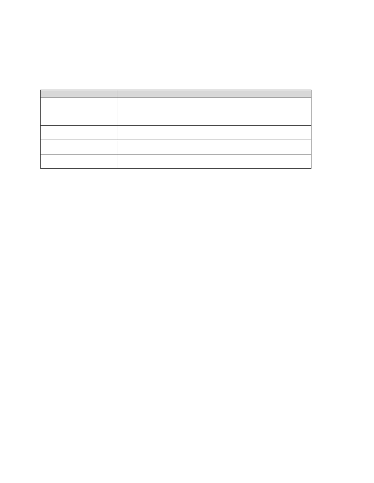
Any errors made in creating or editing the aircraft.cfg file will show up, along with the following
error messages, while an aircraft is being loaded. The error messages are listed in order; that is,
the first error message represents an error early in the aircraft-loading process.
Error Message Description
Aircraft initialization
failure.
Indicates that some essential files are missing from the aircraft
container. If the files are missing, the aircraft wouldn't usually be
displayed in the Select Aircraft dialog box; as a result, this error is
rare.
Failed to start up the
flight model.
The .air file was not loaded successfully.
This is not a Flight
Simulator aircraft model.
The visual model (.mdl) file for this aircraft is not compatible with
Flight Simulator
Visual model could not be
displayed.
An error occurred while loading the visual model (.mdl) file.
The following sections detail each bracketed aircraft.cfg section and its associated parameters.
As you read, you should look at actual aircraft.cfg files to become more familiar with the
structure and syntax of them. They can be found in the individual aircraft containers, and viewed
using any text editor.
Configuration sets and their [fltsim. ] sections
Each [fltsim. ] section of an aircraft.cfg file represents a different version (configuration) of
the aircraft, and is known as a configuration set. Configuration sets allow a single aircraft
container to represent several aircraft, and allow those aircraft to share components.
If there is only one section (labeled [fltsim.0]), it is because there is only one configuration set
in that aircraft container. If there is more than one configuration set (labeled [fltsim.0],
[fltsim.1], [fltsim.2], and so on), each one refers to a different version of the aircraft.
For instance, there are five versions of the Cessna 182, all housed in the same C182 aircraft
container (folder). Each version has its own [fltsim. ] section. The various versions must
vary by their title, and may also vary other items such as the panel, description, or sounds.
While these configuration sets share many components, they can each use different
panels. The panel lines in the respective [fltsim. ] sections thus refer to the
respective panel folder for each aircraft: For example, the panel= parameter in the
[fltsim.1] section is panel=ifr means that this version of the C182 uses the panel files in the
panel.ifr subfolder.
When creating and referencing multiple model, panel, sound, and texture directories, use the
naming convention foldername.extension, where the extension is a unique identifier for that
configuration set (e.g., .ifr). To refer to the folder from the relevant parameter in the aircraft.cfg
file, just specify extension (e.g., panel=ifr). If a parameter isn't explicitly set (as in the
4
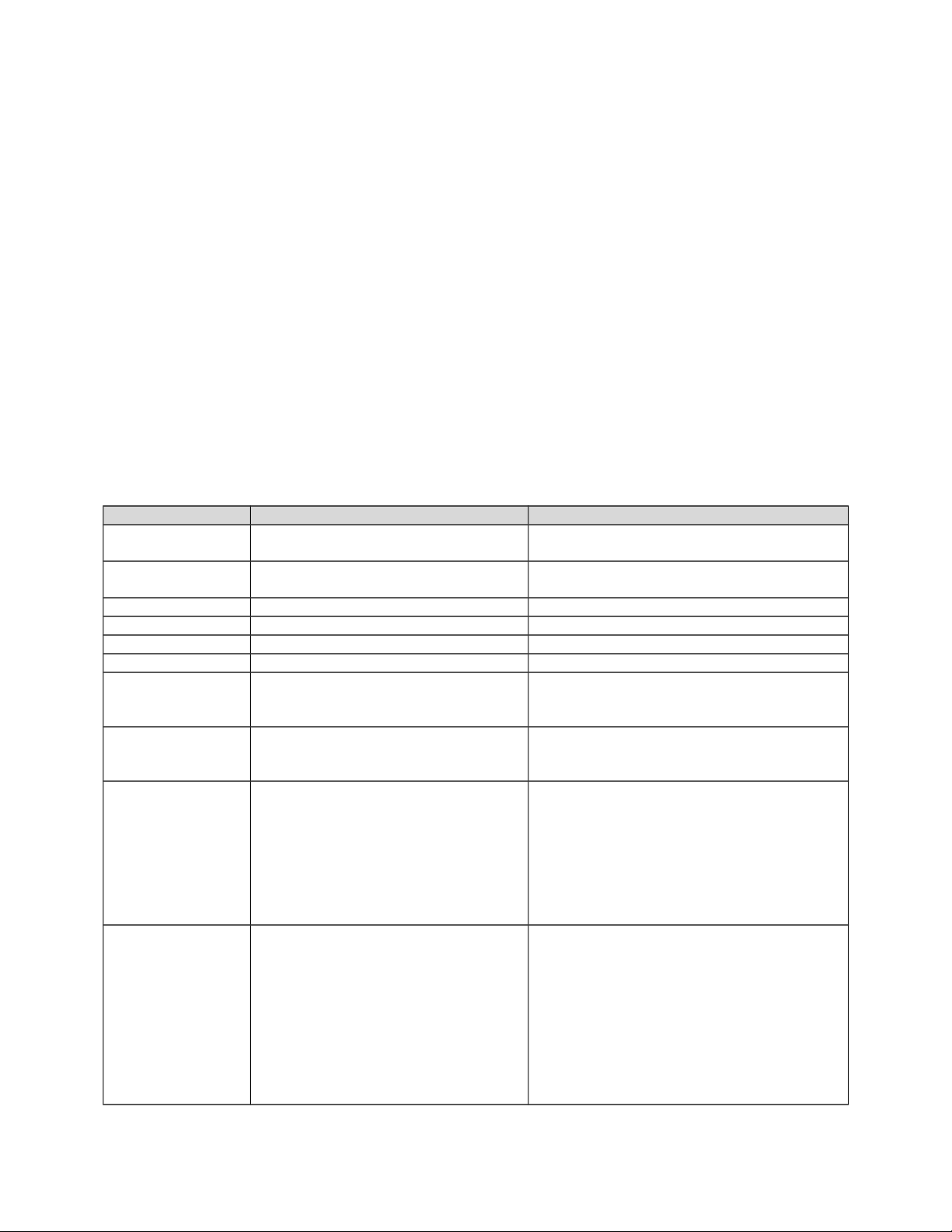
[fltsim.1] section in the example above), it automatically refers to the default (extension-less)
folder.
The parameters in each configuration set can refer to the same files, to different files, or to a mix
of files. While using different panels, all Cessna configurations use the same sounds, and thus the
sound parameters in all three [fltsim. ] sections point to the single “sound” folder in the C182
folder.
Each aircraft defined by a configuration set will appear as a separate listing in the Select Aircraft
dialog box. The fact that multiple “aircraft” share some components is hidden from the user.
From a user’s perspective, they are distinct aircraft (just as if all the common files were
duplicated and included in three distinct aircraft containers). From a developer’s perspective, the
aircraft are really just different configuration sets of the same aircraft. Because they share some
files, they make much more efficient use of disk space.
Within each [fltsim. ] section are parameters that define the details of that particular
configuration set:
Parameter Example Description
title
title= Cessna Skylane 182S
The title of the aircraft that will appear in the
Select Aircraft dialog.
sim
sim= Cessna182S
Specifies which .air (flight model) file
(located in the aircraft folder) to use.
model
model=
Specifies which model folder to reference.
panel
panel=
Specifies which panel folder to reference.
sound
sound=
Specifies which sound folder to reference.
texture
Texture=
Specifies which texture folder to reference.
kb_checklists
kb_checklists=
Cessna182S_check
Specifies which _check.txt file (located in
the aircraft folder) to use on the Checklists
tab of the kneeboard.
kb_reference
kb_reference= Cessna182S_ref
Specifies which _ref.txt file (located in the
aircraft folder) to use on the Reference tab
of the kneeboard.
atc_id
atc_id= N700MS
The tail number displayed on the exterior of
the aircraft. This parameter can also be
edited from the Select Aircraft dialog (if the
atc_id_enable parameter is set to 1). Not
applicable to imported Flight Simulator 98
or Combat Flight Simulator aircraft. .
(Note: custom tail numbers burned into
textures will not be modified by this).
atc_id_color
atc_id_color=0xc6eff7ff
Specifies, in RGB hexadecimal, the color of
the tail number. The first two characters
following the “0x” specify the red value in
hex, the second two characters the green,
and the third set the blue. The final two
characters are unused. Each value can be
between 0 – ff hex, which is 0 to 255
decimal. (Note: custom tail numbers
burned into textures will not be modified by
this).
5

atc_id_font atc_id_font =
Verdana,-11,1,600,0
Specifies how the tail number is displayed
on the aircraft. The first field specifies the
font. The second is the relative height of
the tail number characters. The third field
should be 1, indicating to use your system’s
default character set. The fourth field
represents the relative “heaviness” of the
characters. The final field is a flag that
specifies the characters to be italicized.
The example shown is the default used in
FS. (Note: custom tail numbers burned into
textures will not be modified by this).
atc_parking_types
atc_parking_types=CARGO,RAMP
Specifies the preferred parking for this
aircraft, used by ATC. If this line is omitted,
ATC will determine parking according to the
type of aircraft and parking available. If
multiple values are listed, preference will be
given in the order in which they are listed.
The valid values may be one or more of the
following: RAMP, CARGO, GATE, DOCK,
MIL_CARGO, MIL_COMBAT.
atc_parking_codes
atc_parking_codes=AAL
Specifies an ICAO airline designation so
that ATC can direct the aircraft to a gate
that has also been designated specifically
for that same airline (e.g. AAL for American
Airlines). Documentation on specifying
parking spaces can be found in the Scenery
Facilities Database document.
ui_manufacturer
ui_manufacturer = Cessna
This value identifies the manufacturer sub-
category used to group aircraft in the
“select aircraft” dialog inside FS.
ui_type
ui_type = C182S Skylane
This value identifies the type sub-category
used to group aircraft in the “select aircraft”
dialog inside FS.
ui_variation
ui_variation = White with
blue and purple
This value identifies the variation sub-
category used to group aircraft in the
“select aircraft” dialog inside FS.
description
description=When Cessna saw
how well their Model 180
was selling, they looked
for a way to make it an
even bigger success\s the
answer was the Model 182.
The Cessna 182 Skylane
feels and acts like a
heavier, more powerful
version of its sibling, the
172 Skyhawk. The airplane
is a workhorse and a stable
platform for flying on
instruments. Even with a
full tank, the 182 carries
a family-size useful load
and performs admirably as
an aerial sport utility
vehicle.
The aircraft description can be modified to
say whatever you like about the aircraft.
This information will be displayed in the
“description” box inside FS when the
aircraft is selected. (The \s is used to
produce a semicolon ( ; ) punctuation mark
within the in-game description.)
6
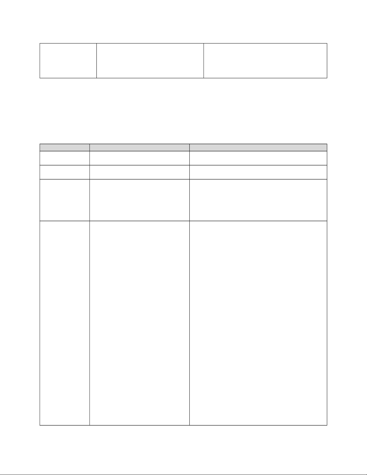
visual_damage
visual_damage=0
Setting this flag to “1” enables visual
damage (e.g. parts breaking off) to be seen
when crashing the aircraft into the scenery.
Note: visual damage will only work if it is
built into the aircraft’s .mdl file.
[General] section
In addition to the [fltsim. ] sections, the [General] section contains information related to ALL
variations of the aircraft. For example, the Cessna 182RG, 182S, and 182S IFR are all the same
TYPE of aircraft, and in actuality, all contain the same flight model. As such, there are some
things that are NOT “variable” across variations:
Parameter Example Description
atc_type
atc_type = Cessna
This is the specific aircraft type that the ATC
system recognizes for this type of aircraft.
atc_model
atc_model = C182
This is the specific aircraft model that the ATC
system recognizes for this type of aircraft.
editable
editable = 0
Determines whether the aircraft can be edited
using the Flight Simulator Aircraft Editor
application. When set to 0, the aircraft will be
read-only in the editor and a copy will have to be
made for editing. When set to 1, the aircraft will
be editable.
performance
performance=Maximum
Speed\t\n145 kts
167 mph\t269
km\/h\n\nCruise
Speed\t\n140 kts
161 mph \t259
km\/h\n\nEngine\t\nTextro
n Lycoming IO-540-AB1A5
230
hp\n\nPropeller\t\nThree-
bladed McCauley constant
speed\n\nMaximum
Range\t\n968 nm
1,114 sm \t1,793
km\n\nService
Ceiling\t\n18,100 ft \t
5,517 m\n\nFuel
Capacity\t\n92 U.S. gal
348 L \n\nEmpty
Weight\t\n1,910 lb \t
866 kg\n\nMaximum Gross
Weight\t\n3,110 lb \t
1,411 kg\n\nLength\t\n29
ft\t 8.84
m\n\nWingspan\t\n36 ft\t
11 m\n\nHeight\t\n9 ft\t
2.77 m\n\nSeating\t\nUp
to 4 \n\nUseful
Load\t\n1,200 lb \t
544 kg
The performance description for the aircraft can
now be edited. The “\t” is a tab character, and
the “\n” is a new-line character. As the flight
model for all variations is the same, the
performance of each variation should also be
identical.
7
[forcefeedback] section
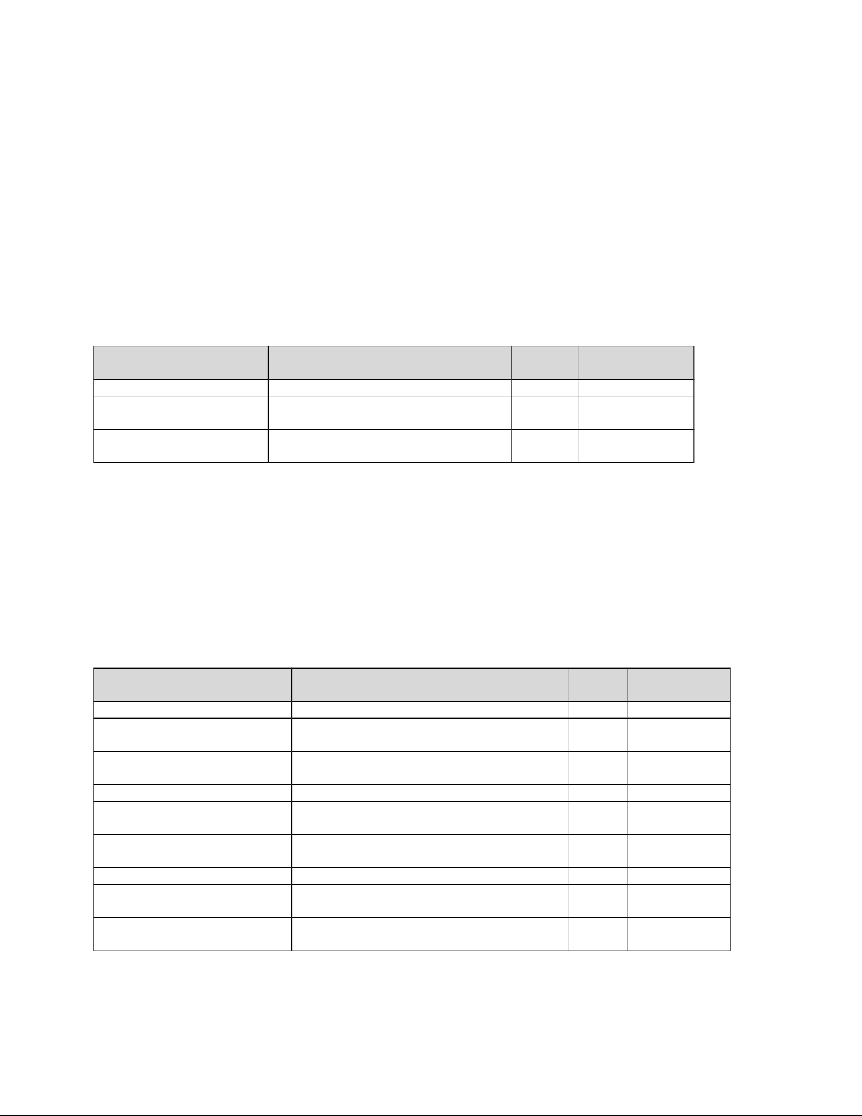
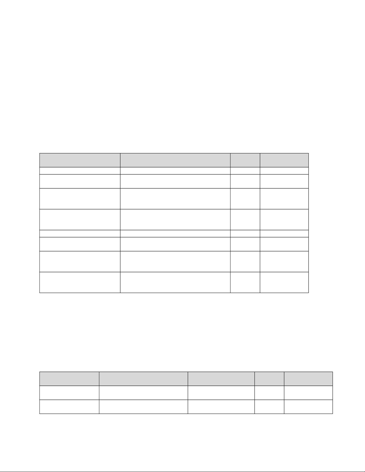
As detailed in the tables below, the parameters in the [forcefeedback] section of an aircraft.cfg
file define the forces generated by that aircraft in the user’s Force Feedback Joystick, so that
different aircraft can have different force effects (a different "feel" in the stick).
Stick shaker parameters
These parameters define the simulated stick shaker force felt in the stick or yoke when flying an
aircraft equipped with a stick shaker (such as the Learjet 45).
Parameter Example (from Lear45
aircraft.cfg)
Data
type
Range
stick_shaker_magnitude
stick_shaker_magnitude=5000
Integer 0–10000
stick_shaker_direction
stick_shaker_direction=0
Integer 0–35999
degrees
stick_shaker_period
stick_shaker_period=111111
Integer 0–2^32-1
microseconds
Gear bump parameters
These parameters define the simulated forces transferred from the airframe and gear drag to the
stick or yoke when the aircraft’s nose and main landing gear is raised or lowered (cycled). In
fixed-gear aircraft this effect won't be felt because, by definition, the landing gear doesn't move.
Different aircraft have different gear geometries that result in each of the gear mechanisms
starting and ending its cycle at a different time. The timing deltas are brief, typically less than a
second between the time that each gear starts and ends its cycle.
Parameter Example (from Lear45 aircraft.cfg) Data
type
Range
gear_bump_nose_magnitude
gear_bump_nose_magnitude=3000
Integer 0–10000
gear_bump_nose_direction
gear_bump_nose_direction=18000
Integer 0–35999
degrees
gear_bump_nose_duration
gear_bump_nose_duration=250000
Integer 0–2^32-1
microseconds
gear_bump_left_magnitude
gear_bump_left_magnitude=2700
Integer 0–10000
gear_bump_left_direction
gear_bump_left_direction=9000
Integer 0–35999
degrees
gear_bump_left_duration
gear_bump_left_duration=250000
Integer 0–2^32-1
microseconds
gear_bump_right_magnitude
gear_bump_right_magnitude=2700
Integer 0–10000
gear_bump_right_direction
gear_bump_right_direction=27000
Integer 0–35999
degrees
gear_bump_right_duration
gear_bump_right_duration=250000
Integer 0–2^32-1
microseconds
8
Ground bumps parameters
These parameters collectively define a composite force that simulates the forces felt through an
aircraft's ground steering controls as the aircraft travels over an uneven surface. The parameters
are divided into two subgroups (numbered 1 and 2), and define the behavior of two distinct
forces. The combination of the two forces (1 and 2), define a composite force that is transferred
to the stick or yoke. The two forces are both sinusoidal periodic forces, with frequencies
determined by the following linear equation:
frequency = (ground_bumps_slope * aircraft_ground_speed) + ground_bumps_intercept
The ground_bumps_magnitude parameters set the magnitude of the force. The
ground_bumps_angle parameters set the direction from which the force is felt.
Parameter Example (from Lear45 aircraft.cfg) Data
type
Range
ground_bumps_magnitude1
ground_bumps_magnitude1=1300
Integer 0–10000
ground_bumps_angle1
ground_bumps_angle1=08900
Integer 0–35999
degrees
ground_bumps_intercept1
ground_bumps_intercept1=3.0
Floating-
point
0–1000000.0
cycles per
second
ground_bumps_slope1
ground_bumps_slope1=0.20
Floating-
point
0–1000000.0
cycles per
second
ground_bumps_magnitude2
ground_bumps_magnitude2=200
Integer 0–10000
ground_bumps_angle2
ground_bumps_angle2=09100
Integer 0–35999
degrees
ground_bumps_intercept2
ground_bumps_intercept2=1.075
Floating-
point
0–1000000.0
cycles per
second
ground_bumps_slope2
ground_bumps_slope2=0.035
Floating-
point
0–1000000.0
cycles per
second
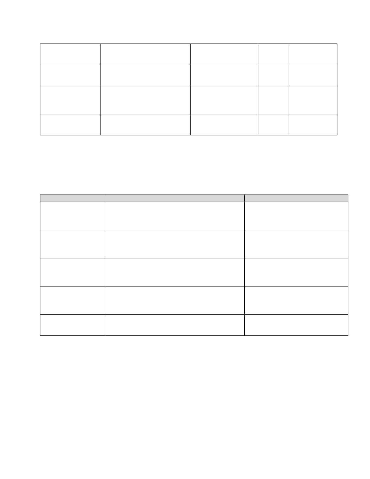
Crash parameters
These parameters define the simulated forces felt in the stick or yoke when the aircraft crashes.
The parameters are divided into two subgroups (numbered 1 and 2), and define the behavior of
two distinct crash-induced forces. The first force is a constant force that lasts for 0.5 seconds.
After 0.5 seconds, it stops and the second force starts. The second force is a periodic square wave
force; its amplitude declines linearly to 0.
Parameter Example (from Lear45
aircraft.cfg)
Description Data
type
Range
crash_magnitude1
crash_magnitude1=10000
Sets the magnitude of
the first force.
Integer 0–10000
crash_direction1
crash_direction1=01000
Sets the direction from
which first force is felt.
Integer 0–35999
degrees
9
crash_magnitude2
crash_magnitude2=10000
Sets the initial
magnitude of the
second force.
Integer 0–10000
crash_direction2
crash_direction2=9000
Sets the direction from
which the second
force is felt.
Integer 0–35999
degrees
crash_period2
crash_period2=75000
Determines the
frequency (frequency
= 1/period) of the
second crash force.
Integer 0–2^32-1
microseconds
crash_duration2
crash_duration2=2500000
Sets the amount of
time that the second
crash force is felt.
Integer 0–2^32-1
microseconds
[Reference_Speeds] section
The values given in this section are also included mainly for use in FSEDIT. However, you may
modify these values by hand, but you are unlikely to see any affects on the aircraft behavior
without running FSEDIT.
Parameter Example Description
flaps_up_stall_speed flaps_up_stall_speed = 54.0 Stall speed of the aircraft in a clean
(flaps up) configuration at standard
sea level conditions, (Knots True
Airspeed, KTAS).
full_flaps_stall_speed
full_flaps_stall_speed = 43.2
Stall speed of the aircraft in a “dirty”
(flaps full down) configuration at
standard sea level conditions,
(Knots True Airspeed, KTAS).
cruise_speed
cruise_speed = 140.0
Typical cruise speed of the aircraft
in a clean (flaps up) configuration at
a typical cruise altitude, (Knots True
Airspeed, KTAS).
max_indicated_speed
max_indicated_speed=175
Maximum design indicated
airspeed. Also referred to as Never
Exceed Speed or “Red Line” of the
aircraft, (Knots Indicated Airspeed)
max_mach
max_mach=0.9
Maximum design mach of the
aircraft. This generally only applies
to turbine airplanes.
[flight_tuning] section
Flight control effectiveness parameters
The following parameters are multipliers on the default "power" of the control surfaces. For
example, a value of 1.1 increases the effectiveness by 10 percent. Likewise, a value of 0.9
decreases the effectiveness by 10 percent. A negative number reverses the normal effect of the
control. Omission of a parameter results in Flight Simulator defaulting to a value of 1.0.
10
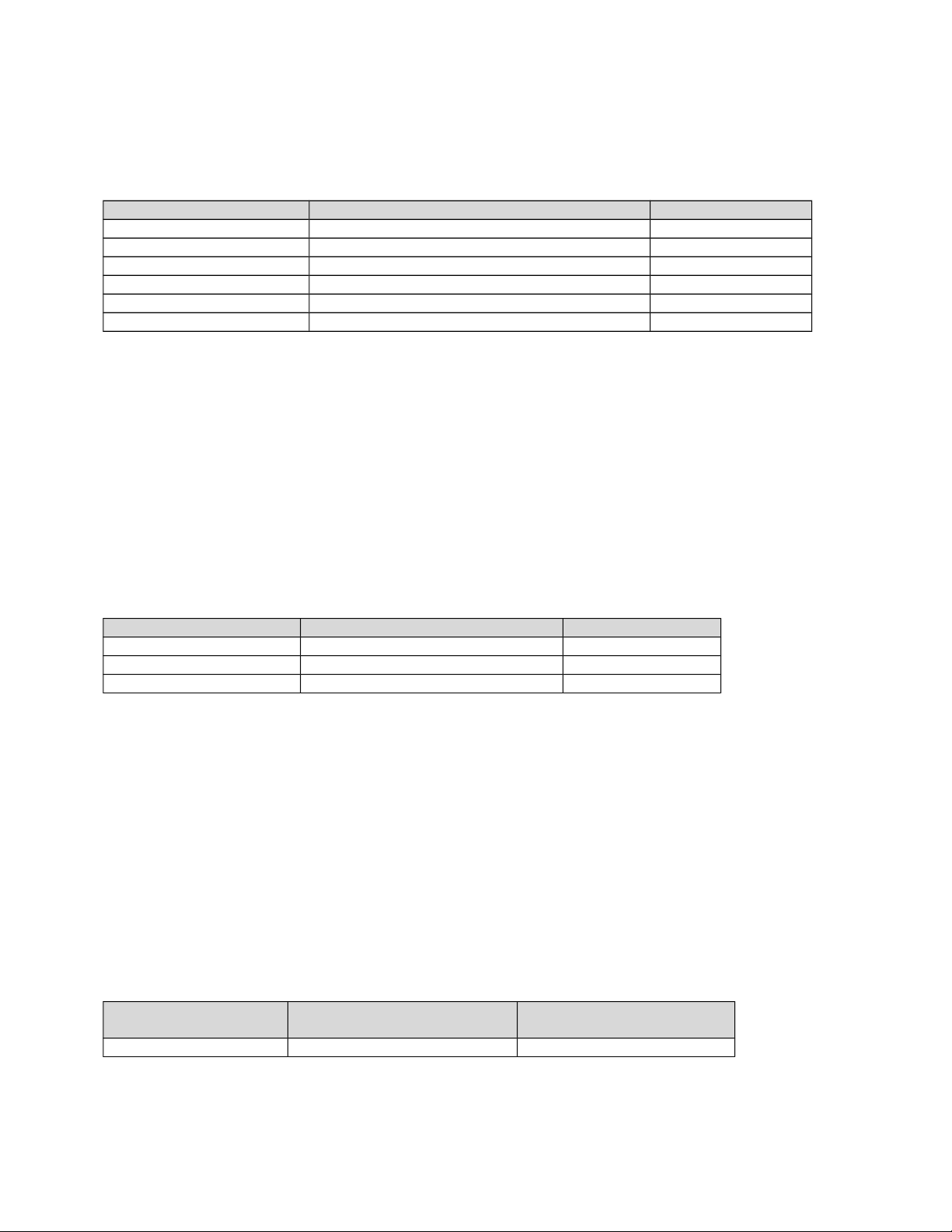
Note: elevator_effectiveness, aileron_effectiveness, and rudder_effectiveness are
adjustable using the Flight Simulator Aircraft Editor.
Parameter Example (from C182 aircraft.cfg) Aerodynamic term
elevator_effectiveness
elevator_effectiveness=1.0
Cmde
aileron_effectiveness
aileron_effectiveness=1.0
Clda
rudder_effectiveness
rudder_effectiveness=1.0
Cndr
elevator_trim_effectiveness
elevator_trim_effectiveness=1.0
Cmdetr
aileron_trim_effectiveness
aileron_trim_effectiveness=1.0
Cldatr
rudder_trim_effectiveness
rudder_trim_effectiveness=1.0
Cndrtr
Stability parameters
The following parameters are multipliers on the default stability (damping effect) about the
corresponding axis of the airplane. For example, a value of 1.1 increases the damping by 10%.
Likewise, a value of 0.9 decreases the damping by 10%. A negative number results in an
unstable characteristic about the axis. A positive damping effect is simply a moment in the
direction opposite of the rotational velocity. Omission of a parameter will result in Flight
Simulator defaulting to a value of 1.0.
Note: These three parameters are adjustable using the Flight Simulator Aircraft Editor
Application.
Parameter Example Aerodynamic term
pitch_stability
pitch_stability=1.0
Cmq
roll_stability
roll_stability=1.0
Clp
yaw_stability
yaw_stability=1.0
Cnr
Lift parameter
The following parameter is a multiplier on the coefficient of lift at zero angle of attack ("cruise
lift" in this context refers to the lift at relatively small angles of attack, which is typical for an
airplane in a cruise condition). This scaling is decreased linearly as angle of attack moves toward
the critical (stall) angle of attack, which prevents destabilizing low speed and stall characteristics
at high angles of attack. Modify this value to set the angle of attack (and thus pitch) for a cruise
condition. A negative value is not advised, as this will result in extremely unnatural flight
characteristics. Omission of this parameter will result in Flight Simulator defaulting to a value of
1.0.
Note: This parameter is adjustable using the Flight Simulator Aircraft Editor Application.
Parameter Example Aerodynamic term for
parameter
cruise_lift_scalar
cruise_lift_scalar=1.0
CL0
11
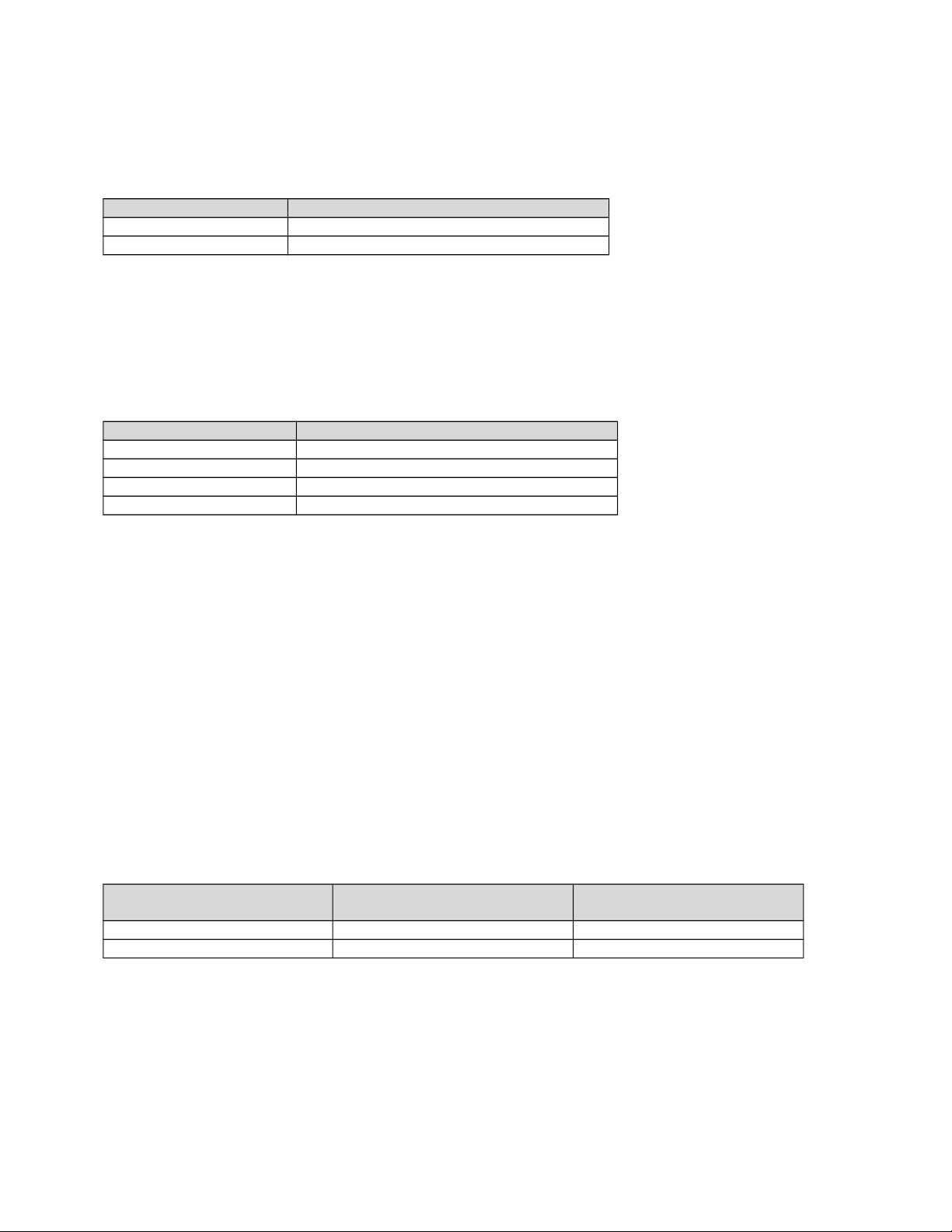
High Angle of Attack parameters
The following parameters are multipliers on the effects on roll and yaw at high angles of attack.
The default values are 1.0.
Parameter Example
hi_alpha_on_roll
hi_alpha_on_roll=1.0
hi_alpha_on_yaw
hi_alpha_on_yaw=1.0
Propeller-induced turning effect parameters
The following parameters are multipliers on the effects induced by rotating propellers These are
often called “left turning tendencies” for clockwise rotating propellers, although MSFS
automatically handles counter-clockwise rotating propellers. The default values are 1.0.
Parameter Example
p_factor_on_yaw
p_factor_on_yaw=1.0
torque_on_roll
torque_on_roll=1.0
gyro_precession_on_roll
gyro_precession_on_roll=1.0
gyro_precession_on_yaw
gyro_precession_on_yaw=1.0
Drag parameters
Drag is the aerodynamic force that determines the aircraft speed and acceleration. There are two
basic types of drag that the user can adjust here. Parasitic drag is composed of two basic
elements: form drag, which results from the interference of streamlined airflow, and skin friction.
Parasite drag increases as airspeed increases. Induced drag results from the production of lift.
Induced drag increases as angle of attack increases.
The following parameters are multipliers on the two respective drag coefficients. For example, a
value of 1.1 increases the respective drag component by 10 percent. A value of 0.9 decreases the
drag by 10 Percent. Negative values are not advised, as extremely unnatural flight characteristics
will result. Omission of a parameter results in Flight Simulator defaulting to a value of 1.0.
Note: These two parameters are adjustable using the Flight Simulator Aircraft Editor
Application.
Parameter Example (from C182
aircraft.cfg)
Aerodynamic term for
parameter
parasite_drag_scalar
parasite_drag_scalar=1.0
Cd0
induced_drag_scalar
induced_drag_scalar=1.0
Cdi
[weight_and_balance] section
The weight and center of gravity of the aircraft can be affected through the following parameters.
The sign convention for positions is positive equals longitudinally forward, laterally to the right,
and vertically upward.
12

Note: In the stock aircraft, the station_load.0, 1, etc. parameters are enclosed in quotation marks.
These are used by internal language translation tools, and are not necessary for in-game use.
Parameter Example Units / format Description
max_gross_weight
max_gross_weight =
3110
pounds Maximum design gross
weight of the aircraft.
This parameter is used
solely in FSEDIT to help
determine the
aerodynamic
coefficients.
empty_weight
empty_weight=1810
pounds Total weight (in pounds)
of the aircraft minus
usable fuel, passengers,
cargo, and expendable
armament (Combat
Flight Simulator aircraft).
If not specified, the value
previously set in the .air
file will be used.
reference_datum_position
reference_datum_posi
tion= 3.6, 0, 0
feet,feet,feet Offset (in feet) of the
aircraft's reference
datum from the standard
Flight Simulator center
point, which is on the
centerline ¼ chord aft of
the leading edge. By
setting the Reference
Datum Position, actual
aircraft loading data can
be used directly
according to the
aircraft's manufacturer. If
not specified, the default
is 0,0,0 (Flight
Simulator's default
center).
empty_weight_CG_position
empty_weight_CG_posi
tion= -3.0, 0, 0
feet,feet,feet Offset (in feet) of the
center of gravity of the
basic empty aircraft (no
fuel, passengers, or
baggage) from the
Reference Datum
Position.
13
station_load.0
station_load.0=170,
-3.0, -1.5,
0.0,Pilot
pounds,feet,
feet,feet
Specifies the weight and
position of passengers
or payload at a station
specified with a unique
number, station_load.N.
The first parameter
number on each line
specifies the weight (in
pounds), followed by the
offset (in feet) of the
station (longitudinal,
lateral, and vertical) from
the Reference Datum
Position. The addition of
stations results in a
corresponding change in
aircraft flight dynamics
due to the change of the
total weight and
moments of inertia. The
final field is the string
name that is used in the
Payload dialog (15
character limit).
Omission of this will
result in a generic
“station” name being
used.
station_load.1
station_load.1=170,
-3.0, 1.5, 0.0,
Front Passenger
pounds,feet,fee
t,feet
Same as above
station_load.2
station_load.2=160,
-6.2, -1.5, 0.0,Rear
Passenger
pounds,feet,fee
t,feet
Same as above
max_number_of_stations
max_number_of_statio
ns=50
number Max Number of Stations
specifies the maximum
number of stations Flight
Simulator will calculate
when the aircraft is
loaded. This allows an
unlimited number of
stations to be specified.
Note that an excessively
large number here
results in a longer load
time for the aircraft when
selected, although there
is no effect on real-time
performance.
14
Moments of Inertia
A moment of inertia (MOI) defines the mass distribution about an axis of an aircraft. A moment
of inertia for a particular axis is increased as mass is increased and/or as the given mass is
distributed farther from the axis. This is largely what determines the inertial characteristics of the
aircraft.
The following weight and balance parameters define the MOIs of the empty aircraft, meaning
that the value should not reflect fuel, passengers, baggage, or expendable armament (Combat
Flight Simulator aircraft). Flight Simulator determines the total MOIs with these influences
within the simulation. The units are slug - ft^2. Omission of a parameter will result in Flight
Simulator defaulting to the value set in the .air file, if one exists.
Parameter Example Description
empty_weight_pitch_MOI
empty_weight_pitch_MOI=1400.0
The moment of inertia
(MOI) about the lateral
axis.
empty_weight_roll_MOI
empty_weight_roll_MOI=1137.0
The moment of inertia
(MOI) about the
longitudinal axis.
empty_weight_yaw_MOI
empty_weight_yaw_MOI=2360.0
The moment of inertia
(MOI) about the vertical
axis.
empty_weight_coupled_MOI
empty_weight_coupled_MOI = 0.0
The moment of inertia
(MOI) about the roll and
yaw axis (usually zero).
These values can be estimated with the following formula:
MOI = EmptyWeight * (D^2 / K)
Where:
Pitch Roll Yaw
D = Length (feet) Wingspan (feet) 0.5* (Length+Wingspan)
K = 810 1870 770
This formula yields only rough estimates. Actual values vary based on aircraft material, installed
equipment, and number of engines and their positions.
15
[fuel] section
This section defines the characteristics of the fuel system, including the tanks, fuel type, and the number
of fuel selectors. The maximum number of selectors supported is 2. This value is intended to match the
number of visual selectors on the instrument panel.
Parameter Example (from C182
aircraft.cfg)
Units Description
Center1
Center2
Center3
LeftMain
LeftAux
LeftTip
RightMain
RightAux
RightTip
External1
External2
LeftMain = -3.85, -2.10, 2.50,
46.0, 0.00
RightMain= -3.85, 2.10, 2.50,
46.0, 0.00
Feet,
Gallons
The
longitudinal,
lateral, and
vertical position
of the tank.
Next are the
usable and
unusable
capacities of
the tanks.
fuel_type
fuel_type=1
1 – Avgas, 2 –
JetA
number_of_tank_selectors
number_of_tank_selectors=1
Number of fuel
tank selectors
(max 4 –
should be less
than or equal to
number of
engines).
electric_pump
electric_pump = 1
Boolean that
sets whether an
electric boost
pump is
available, 0 =
FALSE, 1 =
TRUE.
[GeneralEngineData] section
Every type of aircraft, even a glider, should have this section in the aircraft.cfg file. Basically, this section
describes the type of engine, the number of engines, where the engines are located, and a fuel flow
scalar to modify how much fuel the engine requires to produce the calculated power.
Parameter Example Description
engine_type
engine_type = 0
Integer that identifies what type of
engine is on the aircraft. 0 = piston,
1 = Jet, 2 = None, 3 = Helo-turbine, 4
= Rocket.
engine.0
engine.1
engine.2
engine.3
engine.0 = 2.4, 0..0, 0.0
Offset (in feet) of the engine from the
Reference Datum Position
(longitudinal, lateral and vertical).
Each engine location specified
increases the engine count
(maximum of four engines allowed).
16
fuel_flow_scalar
fuel_flow_scalar = 1.0
Scalar for modifying the fuel flow
required by the engine(s). A value of
less than 1.0 causes a slower fuel
consumption for a given power
setting, a value greater than 1.0
causes the aircraft to burn more fuel
for a given power setting.
min_throttle_limit
min_throttle_limit=0
Defines the minimum throttle position
(percent of max). Normally 0 for
piston aircraft and -0.25 for turbine
airplane engines with reverse thrust.
max_contrail_temperature
max_contrail_temperature=
-39.0
Ambient temperature, in Celsius, in
which engine vapor contrails will turn
on. The default value is about -39
degrees Celsius for turbine engines.
For piston engines, the contrail effect
is turned off unless a temperature
value is set here.
master_ignition_switch
master_ignition_switch=0
1=Available, 0=Not Available
(default). If available, this switch
must be on for the ignition circuit,
and thus the engines, to be operable.
Turning it off will kill all engines.
[piston_engine] section
A piston engine’s power can be determined through a series of equations that represent the
“Otto” cycle of a four-stroke piston engine, multiplied by the number of pistons available. This
section contains all the information Flight Simulator needs to be able to determine how much
power your engine is capable of producing. (Power can also be scaled from the calculated values
generated for piston engines with the “power_scalar” value.)
Parameter Example Description
power_scalar power_scalar = 1.0 Changing this value affects the
amount of power delivered by
th engine to the propellor shaft.
cylinder_displacement cylinder_displacement = 90.3 Cubic inches per cylinder
displacement.
compression_ratio compression_ratio = 8.5 Compression ratio of each
cylinder.
number_of_cylinders number_of_cylinders = 6 Integer value; number of
cylinders in the engine.
number_of_magnetos number_of_magnetos=2 Number of magnetos on the
piston engine. Only values of
1 and 2 are supported.
max_rated_rpm max_rated_rpm = 2400 Maximum rated revolutions per
minute (RPM) of the engine
(red line).
max_rated_hp max_rated_hp = 230 Maximum rated brake
horsepower output of the
engine.
17
fuel_metering_type fuel_metering_type = 0 Integer value indicating the
fuel metering type; 0 = Fuel
Injected, 1 = Gravity
Carburetor, 2 = Aerobatic
Carburetor.
cooling_type cooling_type = 0 Integer value indicating the
method of engine cooling; 0 =
air cooled, 1 = liquid cooled.
normalized_starter_torque normalized_starter_torque = 0.3 This value can be modified to
increase/decrease the torque
supplied by the starter to get
the prop turning. Increase this
value for a greater torque
effect, decrease it for a lower
torque setting.
turbocharged turbocharged = 0 Boolean to indicate if the
engine is turbocharged; 0 =
FALSE, 1 = TRUE.
max_design_mp max_design_mp = 0 If a turbocharger is present,
this value indicates the
maximum design manifold
pressure supplied by the
turbocharger (inHg).
min_design_mp min_design_mp = 0 If a turbocharger is present,
this value indicates the
minimum design manifold
pressure of the turbocharger
(inHg).
critical_altitude critical_altitude = 0 Altitude to which the
turbocharger, if present, will
provide the maximum design
manifold pressure (feet).
emergency_boost_type emergency_boost_type = 0 Integer value indicating the
emergency boost type
available; 0 = None, 1 = Water
Injection, 2 = Methanol/Water
Injection, 3 = War Emergency
Power, (typically used in WWII
combat aircraft).
emergency_boost_mp_offset emergency_boost_mp_offset = 0 Additional manifold pressure
supplied by emergency boost,
if available.
emergency_boost_gain_offset emergency_boost_gain_offset =
0
Multiplier on manifold pressure
due to emergency boost.
fuel_air_auto_mixture fuel_air_auto_mixture = 0 Boolean to indicate if
automatic fuel-to-air mixture is
available; 0 = FALSE, 1 =
TRUE.
auto_ignition auto_ignition = 0 Boolean to indicate if
automatic ignition is available;
0 = FALSE, 1 = TRUE.
18
max_rpm_mechanical_efficiency_
scalar
max_rpm_mechanical_efficiency
_scalar = 1.0
Scalar value that can be
modified to tune the
mechanical efficiency of the
engine at maximum rpm.
Increase this value to increase
the mechanical efficiency,
decrease it to decrease the
mechanical efficiency.
idle_rpm_mechanical_efficiency_
scalar
idle_rpm_mechanical_efficiency
_scalar = 1.0
Scalar value that can be
modified to tune the
mechanical efficiency of the
engine at idle rpm. Increase
this value to increase the
mechanical efficiency,
decrease it to decrease the
mechanical efficiency.
max_rpm_friction_scalar max_rpm_friction_scalar = 1.0 Scalar value that can be
modified to tune the internal
friction of the engine at
maximum rpm. Increase this
value to increase the friction,
decrease it to decrease the
friction.
idle_rpm_friction_scalar idle_rpm_friction_scalar = 1.0 Scalar value that can be
modified to tune the internal
friction of the engine at idle
rpm. Increase this value to
increase the friction, decrease
it to decrease the friction, (can
be used to tune the rpm at
which the engine idles).
[propeller] section
The thrust generated by a given propeller is a function of the power delivered through the
propeller shaft, RPM, blade angle, airplane speed, and ambient density. Note: This parameter is
adjustable using the Flight Simulator Flight Dynamics Editor portion of the FSEDIT tool.
Parameter Example Description
thrust_scalar thrust_scalar = 1.0 Parameter that scales the calculated
thrust provided by the propeller.
propeller_type propeller_type = 0 Integer that identifies what type of
propeller is on the aircraft. 0 = Constant
Speed, 1 = Fixed Pitch.
propeller_diameter propeller_diameter = 6.8 Diameter of propeller blades, tip to tip, in
feet.
propeller_blades propeller_blades = 2 Integer value indicating the number of
blades on the propeller (2, 3 or 4).
propeller_moi propeller_moi = 5.7 Propeller moment of inertia, (slug – ft
2
).
beta_max beta_max = 31.8 Maximum blade pitch angle for constant
speed prop (degrees). (Not used if fixed
pitch.)
19
beta_min beta_min = 17.0 Minimum blade pitch angle for constant
speed prop (degrees). (Not used if fixed
pitch.)
min_gov_rpm min_gov_rpm = 1400 The minimum RPM controlled by the
governor for a constant speed prop.
prop_tc prop_tc = 0.1 Time constant for prop
gear_reduction_ratio gear_reduction_ratio = 1.0 The reduction ratio from the engine
output RPM to prop RPM.
fixed_pitch_beta fixed_pitch_beta = 20 Blade pitch angle for fixed pitch prop
(degrees). (Not used if constant speed.)
low_speed_theory_limit low_speed_theory_limit = 80 The speed at which low-speed propeller
theory gets blended into the high speed
propeller theory, (feet/second).
prop_sync_available prop_sync_available = 0 Boolean to indicate if propeller-sync is
available (twin engine aircraft); 0 =
FALSE, 1 = TRUE.
prop_deice_available prop_deice_available = 0 Boolean to indicate if propeller de-icing is
available; 0 = FALSE, 1 = TRUE.
prop_feathering_available prop_feathering_available =
0
Boolean to indicate if prop feathering is
available (constant speed prop only); 0 =
FALSE, 1 = TRUE.
prop_auto_feathering_avail
able
prop_auto_feathering_availa
ble = 0
Boolean to indicate if prop auto-
feathering is available (constant speed
prop only); 0 = FALSE, 1 = TRUE.
min_rpm_for_feather min_rpm_for_feather = 0 Minimum RPM at which the prop will
feather (if feathering is available).
beta_feather beta_feather = 0 Propeller pitch angle when feathered
(degrees).
power_absorbed_cf power_absorbed_cf = 0 Coefficient of friction power absorbed by
propeller.
defeathering_accumulators
_available
defeathering_accumulators_
available = 0
Boolean to indicate if de-feathering
accumulators are available; 0 = FALSE,
1 = TRUE.
feathering_switches feathering_switches=0 Boolean indicating if feathering switches
are available. 0 = FALSE, 1 = TRUE.
Feathering switches (as found on the
Douglas DC3), allow the pilot to
automatically feather the propeller via a
switch, regardless of the propeller lever
position.
prop_reverse_available prop_reverse_available = 0 Specifies the scalar on the calculated
propeller reverser effect. A value of 0
will cause no reverse thrust to be
available. A value of 1.0 will cause the
theoretical normal thrust to be available.
Other values will scale the normal
calculated value accordingly.
minimum_on_ground_beta minimum_on_ground_beta =
0
Minimum blade pitch angle when the
aircraft is on the ground (degrees).
minimum_reverse_beta minimum_reverse_beta = 0 Minimum blade pitch angle when the
propeller is in reverse (degrees).
20
number_of_propellers number_of_propellers=2 By default, the number of propellers will
be set to the number of engines. The
Wright Flyer is an example of where
there are a different number of propellers
than engines. The number of propellers
must not be less than the number of
engines.
engine_map engine_map = 0,0 By default, propeller 1 is driven by
engine 1, propeller 2 by engine 2, and so
on. This parameter allows the propellers
to be driven by other than the
corresponding engine. The series of
numbers, separated by commas,
represent the engine index which drives
the propeller. In the example (from the
Wright Flyer), both propellers are driven
by the first engine (engine.0). The
corresponding torque from the props will
also affect the driving engines
appropriately.
propeller.0,1,…n propeller.0 = -6.9,-6.2,3.1 By default, the propeller thrust is located
at the position specified for the
corresponding engine in the
[GeneralEngineData] section. This
parameter allows for the propeller to be
located at the specified offset
(longitudinal, lateral, vertical) in feet from
the engine that is driving it. Example is
from the Wright Flyer, which has two
propellers offset from the engine. The
propeller position is where the thrust is
applied to the aircraft.
[TurbineEngineData] section
A turbine engine ignites fuel and compressed air to create thrust. These parameters define the
power (thrust) output of a given jet engine.
Parameter Example (from lear45 aircraft.cfg) Description
fuel_flow_gain fuel_flow_gain = 0.0025 Fuel flow gain constant.
inlet_area
inlet_area = 4.2895
Engine nacelle inlet area, (ft
2
)
rated_N2_rpm
rated_N2_rpm = 29920
Second stage compressor rated
RPM.
static_thrust
static_thrust = 3500
Maximum rated static thrust at sea
level (lbs).
afterburner_available
afterburner_available = 0
Boolean value to indicate if an
afterburner is available; 0 =
FALSE, 1 = TRUE.
21
reverser_available
reverser_available = 1
Specifies the scalar on the
calculated reverse thrust effect. A
value of 0 will cause no reverse
thrust to be available. A value of
1.0 will cause the theoretical
normal reverse thrust to be
available. Other values will scale
the normal calculated value
accordingly.
[jet_engine] section
The thrust_scalar parameter scales the calculated thrust for jet engines (from the
[TurbineEngineData] section).
Note: his parameter is adjustable using the Flight Simulator Flight Dynamics Editor.
Parameter Example (from lear45 aircraft.cfg)
thrust_scalar
thrust_scalar = 1.0
[turboprop_engine] section
The amount of power generated by an engine and the power required for a propeller to turn
through the air determine the increase and decrease of the RPM. A turboprop engine is really a
combination of a turbine engine and a propeller. The values in the [turboprop_engine] section
are included to modify values specific to the turboprop.
Note: These parameter is adjustable using the Flight Simulator Flight Dynamics Editor.
Parameter Example (from beech_king_air_350
aircraft.cfg)
Description
power_scalar power_scalar = 1.0 Changing this value affects the
amount of power delivered by the
engine to the propeller shaft.
maximum_torque
maximum_torque = 3270
Maximum shaft-torque available
from the engine (ft-lbs).
[contact_points] section
You can configure and adjust the way aircraft reacts to different kinds of contact, including
landing gear contact and articulation, braking, steering, and damage accrued through excessive
speed.
You can also configure each contact point independently for each aircraft, and there is no limit to
the number of points you can add. The data for configuring the points are placed in the
[contact_points] section of the aircraft.cfg. When importing an aircraft that does not contain this
set of data, the program will generate the data from the .air file the first time the aircraft is
loaded, and then write it to the aircraft.cfg.
22

It may be useful to first look at the .cfg file of an existing aircraft; you can learn a lot from the
many developer comments, which are followed by two slashes (//).
Each contact point contains a series of values that define the characteristics of the point,
separated by commas. Each point's data set takes the form “point.n=”, where “n” is the index to
the particular point, followed by the data.
Example:
[contact_points]
point.0= 1, -18.0, 0, -3.35, 3200, 0, 0.50,180, 0.25, 2.5, 0.90, 1.0, 4.0, 0, 0, 200
Below is a description of each element of the example contact point data set:
Parameter Element Description
1 (1) Class Integer defining the type of contact
point: 0 = None, 1 = Wheel, 2 =
Scrape, 3 = Skid, 4 = Float, 5 =
Water Rudder
2 (-18.0)
Longitudinal Position
The longitudinal distance of the point
from the defined reference datum
(feet). Positive is forward (out the
nose).
3 (0)
Lateral Position
The lateral distance of the point from
the defined reference datum (feet).
Positive is starboard (right, as
viewed from the top with the airplane
pointing “up”).
4 (-3.35)
Vertical Position
The vertical distance of the point
from the defined reference datum
(feet). Positive is up.
5 (3200)
Impact Damage Threshold
The speed at which an impact with
the ground can cause damage
(feet/min).
6 (0)
Brake Map
Defines which brake input drives the
brake (wheels only). 0 = None, 1 =
Left Brake, 2 = Right Brake.1
7 (0.50)
Wheel Radius
Radius of the wheel (feet).
8 (180)
Steering Angle
The maximum angle (positive and
negative) that a wheel can pivot
(degrees).
9 (0.25)
Static Compression
This is the distance a landing gear is
compressed when the empty aircraft
is at rest on the ground (feet). This
term defines the “strength” of the
strut, where a smaller number will
increase the “stiffness” of the strut.
10 (2.5)
Ratio of Maximum
Compression to Static
Compression
Ratio of the max dynamic
compression available in the strut to
the static value. Can be useful in
coordinating the “compression” of the
strut when landing.
23

11 (0.90)
Damping Ratio
This ratio describes how well the
ground reaction oscillations are
damped. A value of 1.0 is
considered critically damped,
meaning there will be little or no
osciallation. A damping ratio of 0.0
is considered undamped, meaning
that the oscillations will continue with
a constant magnitude. Negative
values result in an unstable ground
handling situation, and values
greater than 1.0 might also cause
instabilities by being “over” damped.
Typical values range from 0.6 to
0.95.
12 (1.0)
Extension Time
The amount of time it takes the
landing gear to fully extend under
normal conditions (seconds). A
value of zero indicates a fixed gear.
13 (4.0)
Retraction Time
The amount of time it takes the
landing gear to fully retract under
normal conditions (seconds). A
value of zero indicates a fixed gear.
14 (0)
Sound Type
This integer value will map a point to
a type of sound:
0 = Center Gear,
1 = Auxiliary Gear,
2 = Left Gear,
3 = Right Gear,
4 = Fuselage Scrape,
5 = Left Wing Scrape,
6 = Right Wing Scrape,
7 = Aux1 Scrape,
8 = Aux2 Scrape,
9 = Tail Scrape.
15 (0)
Airspeed Limit
This is the speed at which landing
gear extension becomes inhibited
(knots). Not used for scrape points
or non-retractable gear.
16 (200)
Damage from Airspeed
The speed above which the landing
gear accrues damage (knots). Not
used for scrape points or non-
retractable gear.
In addition to the specific data for each contact point, there are “global” [contact_point]
parameters that are also used:
Parameter Example Description
max_number_of_points max_number_of_points = 21 Integer value indicating the
maximum number of points the
program will look for in the
[contact_points] section.
24

static_pitch
static_pitch = 3.82
The static pitch of the aircraft when
at rest on the ground (degrees).
The program uses this value to
position the aircraft at startup, in
slew, and at any other time when
the simulation is not actively
running.
static_cg_height
static_cg_height = 3.015
The static height of the aircraft
when at rest on the ground (feet).
The program uses this value to
position the aircraft at startup, in
slew, and at any other time when
the simulation is not actively
running.
gear_system_type
gear_system_type=1
This parameter defines the system
type which drives the gear
extension and retraction.
0 = electrical,
1 = hydraulic,
2 = pneumatic,
3 = manual,
4 = none.
[gear_warning_system] section
The following parameters define the functionality of the aircraft’s gear warning system. This is
generally a function of the throttle lever position and the flap deflection.
Parameter Example Description
gear_warning_available
gear_warning_availiable =
1
Sets the type of gear warning
system available on the aircraft. 0 =
None, 1 = Normal, 2 = Amphibian
(audible alert for water vs. land
setting).
pct_throttle_limit
pct_throttle_limit = 0.1
The throttle limit, below which the
gear warning will activate if the gear
is not down and locked while the
flaps are deflected to at least the
setting for flap_limit_idle below.
This flap limit can be 0 so that the
warning effectively is a function of
the throttle. 0 = idle, 1.0 = Max
throttle.
25
flap_limit_idle
flap_limit_idle = 0
In conjunction with the throttle limit
specified above, this limit is the flap
deflection, above which the warning
will activate if the gear is not down
and locked while the throttle is
below the limit specified above. By
setting this limit to a value greater
than zero, the pilot can reduce the
throttle to idle without activating the
warning. This is often utilized in jets
to decelerate/descend the aircraft.
flap_limit_power flap_limit_power = 30 The flap limit, above which the
warning will activate (regardless of
throttle position).
[brakes] section
The following parameters define the
Parameter Example Description
parking_brake = 1 Boolean setting if a parking brake is
available on the aircraft.
0 = FALSE, 1 = TRUE.
toe_brakes_scale
= 1.0
Sets the scaling of the braking
effectiveness. 1.0 is the default.
0.0 scales the brakes to no
effectiveness.
differential_braking_scale
= 0
Differential braking is a function of
the normal “both” brakes on and the
rudder pedal input. The amount of
difference between the left and right
brake is scaled by this value. 1.0 is
the normal setting if differential
braking is desired (particularly on
tailwheel airplanes). 0.0 is the
setting if no differential braking is
desired.
[airplane_geometry] section
The airplane [airplane_geometry] section has been added mainly for use with the FSEDIT
application and the ability to create a flight model from aircraft geometrical input. Although you
can edit these values by hand here in the aircraft.cfg file, modification of SOME of these
variables will have little to no effect on airplane performance, as the flight model aerodynamic
coefficients are all still located in the [aircraft_title].air file. The FSEDIT program will change
the aerodynamic coefficients in the .air file based on the values in this section (and others), but
changing the values in the aircraft.cfg file WITHOUT running the FSEDIT application will
result in little, if any, noticeable changes in aircraft behavior. Nonetheless, these values have
been exposed for your convenience.
26
Parameter Example (from C182
aircraft.cfg)
Description
wing_area wing_area = 176.0 Area of the top surface of the entire wing
tip-to-tip (ft
2
).
wing_span wing_span = 36.0 Wing span is the horizontal distance from
wing-tip to wing-tip (feet).
wing_root_chord wing_root_chord = 4.9 Length of the wing chord (leading edge to
trailing edge) at the intersection of the
wing and the fuselage (feet).
wing_dihedral wing_dihedral = 1.7 When looking at the front of an aircraft,
this is the angle between the wing leading
edge and a horizontal line parallel to the
ground (degrees).
wing_incidence wing_incidence = 1.5 When looking at the side of an aircraft
from the wing tip, this is the angle the
mean wing chord makes with a horizontal
line parallel to the ground, (degrees).
Note: this parameter is not used in the
real-time aerodynamic calculations, as it
is already factored into the lift and drag
parameters. It will however influence the
calculation of the lift and drag constants
and tables generated through Fsedit.
wing_twist wing_twist This is the difference in wing incidence
from the root chord and the tip chord of
the wing, (degrees). Also known as
“wash-out.”
oswald_efficiency_factor oswald_efficiency_factor
= 0.7
This is a measure of the aerodynamic
efficiency of the wing. A theoretically
“perfect” wing will have an OEF of 1.0.
wing_winglets_flag wing_winglets_flag = 0 Boolean to indicate if the aircraft
incorporates the use of winglets; 0 =
FALSE, 1 = TRUE.
wing_sweep wing_sweep = 0.0 When looking down on top of an aircraft,
this is the angle the wing leading edge
makes with a horizontal line perpendicular
to the fuselage, (degrees).
wing_pos_apex_lon wing_pos_apex_lon =
-2.4
Longitudinal distance of the wing apex
(measured at centerline of aircraft) from
defined reference point (feet). This
distance is measured POSITIVE in the
forward (out the aircraft nose) direction.
wing_pos_apex_vert wing_pos_apex_vert =
0.0
Vertical distance of the wing apex
(measured at centerline of aircraft) from
defined reference point (feet). This
distance is measured POSITIVE in the UP
direction.
htail_area htail_area = 39.0 Area of the top surface of the entire
horizontal tail (tip-to-tip) (ft
2
).
htail_span htail_span = 11.7 Horizontal tail span is the horizontal
distance from horizontal tail-tip to
horizontal tail -tip (feet).
27
htail_pos_lon htail_pos_lon = -18.3 Longitudinal distance of the horizontal tail
apex (measured at centerline of aircraft)
from defined reference point (feet). This
distance is measured POSITIVE in the
forward (out the aircraft nose) direction.
htail_pos_vert htail_pos_vert = 0.0 Vertical distance of the horizontal tail apex
(measured at centerline of aircraft) from
defined reference point, (feet). This
distance is measured POSITIVE in the UP
direction.
htail_incidence htail_incidence = 3.2 When looking at the side of an aircraft
from the horizontal tail tip, this is the angle
the mean horizontal tail chord makes with
a horizontal line parallel to the ground
(degrees).
htail_sweep htail_sweep = 10.0 When looking down on top of an aircraft,
this is the angle the horizontal tail leading
edge makes with a horizontal line
perpendicular to the fuselage (degrees).
vtail_area vtail_area = 18.0 Area of the surface of one side of the
vertical tail (fuselage-to-tip) (ft
2
).
vtail_span vtail_span = 4.8 Vertical tail span is the vertical distance
from the vertical tail-fuselage intersection
to the tip of the vertical tail (feet).
vtail_sweep vtail_sweep = 40.0 When looking at the side of the vertical
tail, this is the angle the vertical tail
leading edge makes with a vertical line
perpendicular to the fuselage (degrees).
vtail_pos_lon vtail_pos_lon = -16.2 Longitudinal distance of the vertical tail
apex (measured at centerline of aircraft)
from defined reference point, (feet). This
distance is measured POSITIVE in the
forward (out the aircraft nose) direction.
vtail_pos_vert vtail_pos_vert = 1.5 Vertical distance of the vertical tail apex
(measured at centerline of aircraft) from
defined reference point (feet). This
distance is measured POSITIVE in the UP
direction.
elevator_area elevator_area = 16.6 Area of the top surface of the entire
elevator (tip-to-tip) (ft
2
).
aileron_area aileron_area = 18.3 Area of the top surface of all the ailerons
on the wing (ft
2
).
rudder_area rudder_area = 6.7 Area of the side surface of the entire
rudder (ft
2
).
elevator_up_limit elevator_up_limit = 28.0 Angular limit of the elevator when
deflected “up” (degrees).
elevator_down_limit elevator_down_limit =
21.0
Angular limit of the elevator when
deflected “down” (degrees).
aileron_up_limit aileron_up_limit = 20.0 Angular limit of the aileron when deflected
“up” (degrees).
aileron_down_limit aileron_down_limit = 15.0 Angular limit of the aileron when deflected
“down” (degrees).
rudder_limit rudder_limit = 24.0 Angular limit of the rudder deflection
(degrees).
28
elevator_trim_limit elevator_trim_limit = 19.5 Angular limit of the elevator trim tab
(degrees).
spoiler_limit spoiler_limit = 0.0 Angular limit of the wing spoilers on an
aircraft, (degrees). If this limit is zero, no
spoilers exist for the aircraft.
spoilerons_available spoilerons_available = 0 Boolean to indicate if the spoilers also
behave as “spoilerons” for roll control (if
spoilers are available): 0 = FALSE, 1 =
TRUE.
aileron_to_spoileron_gain aileron_to_spoileron_gain
= 0
If spoilerons are available, this value is
the constant used in determining the
amount of spoiler deflection per aileron
deflection.
spoiler_handle_available spoiler_handle_available
=0
Boolean that configures the airplane with
manual control of the spoiler deflections.
0 = FALSE, 1 = TRUE.
min_ailerons_for_spoilero
ns
min_ailerons_for_spoilero
ns = 0
This value indicates at what aileron
deflection the spoilers are become active
for roll control, (degrees).
min_flaps_for_spoilerons min_flaps_for_spoilerons
= 0
This value indicates at what minimum flap
handle position the spoilerons become
active.
aileron_to_rudder_scale aileron_to_rudder_scale=
0
This value sets the ratio of rudder to
aileron input. For example, a value of 0.4
would result in 40% rudder deflection for
100% aileron control input.
[flaps.n] section
For each flap set that is on the aircraft, a corresponding [flaps.set] section should exist. Most general
aviation aircraft and smaller jets only have one set of flaps (trailing edge), but it is typical for the larger
commercial aircraft to have a set of leading edge flaps in addition to the trailing edge flaps. The number
of flap sets are determined by the number of [flaps.n] sections contained in the aircraft.cfg file.
The following table provides a description of each term in the [flaps.0] section for the Cessna 182S:
Parameter Example Description
type type = 1 Integer value that indicates if this is
a leading edge or trailing edge flap
set; 1 = trailing edge, 2 = leading
edge.
span-outboard
span-outboard = 0.5
The percentage of half-wing span
the flap extends to (from the wing-
fuselage intersection).
extending-time
extending-time = 5
Time it takes for the flap set to
extend to the fullest deflection angle
specified (seconds).
29

flaps-position.0
flaps-position.1
flaps-position.2
flaps-position.3
flaps-position.0 = 0
flaps-position.1 = 10
flaps-position.2 = 20
flaps-position.3 = 30
Each element of the flaps-position
array indicates the deflection angle
to which the flaps will deflect
(degrees). The largest deflection
angle will be the one used for full
flap deflection.
damaging-speed damaging-speed = 250 Speed at which the flaps begin to
accrue damage (Knots Indicated
Airspeed, KIAS).
blowout-speed blowout-speed = 300 Speed at which the flaps depart the
aircraft (Knots Indicated Airspeed,
KIAS).
lift_scalar lift_scalar = 1.0 The percentage of total lift due to
flap deflection that this flap set is
responsible for at full deflection.
drag_scalar drag_scalar = 1.0 The percentage of total drag due to
flap deflection that this flap set is
responsible for at full deflection.
pitch_scalar pitch_scalar = 1.0 The percentage of total pitch due to
flap deflection that this flap set is
responsible for at full deflection.
system_type system_type = 0 Integer value that indicates what
type of system drives the flaps to
deflect:
0 = Electric,
1 = Hydraulic,
2 = Pneumatic,
3 = Manual,
4 = None.
tailwheel_lock tailwheel_lock=0 Boolean defining if a tailwheel lock
is available (applicable only on
tailwheel airplanes).
0 = FALSE, 1 = TRUE.
[electrical] section
These parameters configure the characteristics of the aircraft's electrical system and its
components. Each aircraft has a battery as well as an alternator or generator for each engine.
Below is a table of [electrical] section parameters shown with typical default values (the
values Flight Simulator uses if the parameters are omitted). The default Min Voltage equals
0.7*Max Battery Voltage. The list of components also reflects all of the systems currently linked
to the electrical system. If a component is included in the list but the aircraft does not actually
have that system, the component is simply ignored.
30
Parameter Example (with default
values that the simulation
uses if the line is omitted)
Units/format* (see
note below)
Description
max_battery_voltage
max_battery_voltage =
24.0
volts The maximum voltage
to which the battery can
be charged. It is also
the voltage available
from the battery when
the aircraft is initialized.
The battery voltage will
decrease from this if the
generators or
alternators are not
supplying enough
current to meet the
demand of the active
components.
generator_alternator
_voltage
generator_alternator_
voltage = 28.0
volts The voltage provided by
a fully functioning
alternator or generator.
max_generator
_alternator_amps
max_generator_alterna
tor_amps = 60.0
amps The maximum current
(amperage) provided by
a fully functioning
alternator or generator.
electric_always
_available
electric_always_avail
able = 0
This flag enables
electrical power
regardless of the state
of the battery or circuit.
flap_motor
flap_motor = 0, 5 ,
17.0
Bus type, max amp
load, min voltage
See notes below.
gear_motor
gear_motor = 0, 5 ,
17.0
Bus type, max amp
load, min voltage
See notes below.
autopilot
autopilot = 0, 5 ,
17.0
Bus type, max amp
load, min voltage
See notes below.
avionics_bus
avionics_bus = 0, 10,
17.0
Bus type, max amp
load, min voltage
See notes below.
avionics
avionics = 1, 5 ,
17.0
Bus type, max amp
load, min voltage
See notes below.
pitot_heat
pitot_heat = 0, 15 ,
17.0
Bus type, max amp
load, min voltage
See notes below.
additional_system
additional_system =
0, 20, 17.0
Bus type, max amp
load, min voltage
See notes below.
marker_beacon
marker_beacon = 1,
2 , 17.0
Bus type, max amp
load, min voltage
See notes below.
gear_warning
gear_warning = 0, 2 ,
17.0
Bus type, max amp
load, min voltage
See notes below.
fuel_pump
fuel_pump = 0, 5 ,
17.0
Bus type, max amp
load, min voltage
See notes below.
starter1
starter1 = 0, 20,
17.0
Bus type, max amp
load, min voltage
See notes below.
starter2
starter2 = 0, 20,
17.0
Bus type, max amp
load, min voltage
See notes below.
31
starter3
starter3 = 0, 20,
17.0
Bus type, max amp
load, min voltage
See notes below.
starter4
starter4 = 0, 20,
17.0
Bus type, max amp
load, min voltage
See notes below.
light_nav
light_nav = 0, 5 ,
17.0
Bus type, max amp
load, min voltage
See notes below.
light_beacon
light_beacon = 0, 5 ,
17.0
Bus type, max amp
load, min voltage
See notes below.
light_landing
light_landing = 0,
5 , 17.0
Bus type, max amp
load, min voltage
See notes below.
light_taxi
light_taxi = 0, 5 ,
17.0
Bus type, max amp
load, min voltage
See notes below.
light_strobe
light_strobe = 0, 5 ,
17.0
Bus type, max amp
load, min voltage
See notes below.
light_panel
light_panel = 0, 5 ,
17.0
Bus type, max amp
load, min voltage
See notes below.
light_cabin
light_cabin = 0, 5 ,
17.0
Bus type, max amp
load, min voltage
See notes below
prop_sync
prop_sync = 0, 15 ,
17.0
Bus type, max amp
load, min voltage
See notes below.
auto_feather
auto_feather = 0,
15 , 17.0
Bus type, max amp
load, min voltage
See notes below.
auto_brakes
auto_brakes = 0, 15 ,
17.0
Bus type, max amp
load, min voltage
See notes below.
standby_vacuum
standby_vacuum = 0,
15 , 17.0
Bus type, max amp
load, min voltage
See notes below.
hydraulic_pump
hydraulic_pump = 0, 2
, 17.0
Bus type, max amp
load, min voltage
See notes below.
fuel_transfer_pump
fuel_transfer_pump =
0, 5 , 17.0
Bus type, max amp
load, min voltage
See notes below.
propeller_deice
propeller_deice = 0,
5 , 17.0
Bus type, max amp
load, min voltage
See notes below.
light_recognition
light_recognition =
0, 5 , 17.0
Bus type, max amp
load, min voltage
See notes below.
light_wing
light_wing = 0, 5 ,
17.0
Bus type, max amp
load, min voltage
See notes below.
light_logo
light_logo = 0, 5 ,
17.0
Bus type, max amp
load, min voltage
See notes below.
directional_gyro
directional_gyro
= 0, 5 , 17.0
Bus type, max amp
load, min voltage
See notes below.
directional_gyro
_slaving
directional_gyro_slav
ing
= 0, 5 , 17.0
Bus type, max amp
load, min voltage
See notes below.
32
Notes:
• Bus Type specifies which bus in the electrical system the component is connected to,
according to the following bus type codes:
Bus
Type
Bus
0 Main Bus (most components connected here)
1 Avionics Bus
2 Battery Bus
3 Hot Battery Bus (bypasses Master switch)
4 Generator/Alternator Bus 1 (function of engine 1)
5 Generator/Alternator Bus 2 (function of engine 2)
6 Generator/Alternator Bus 3 (function of engine 3)
7 Generator/Alternator Bus 4 (function of engine 4)
• Max Amp Load is the current required to power the component, and of course becomes
the additional load on the electrical system.
• Min Voltage is the minimum voltage required from the specified bus for the component
to function.
With the following parameter, an aircraft can be configured to have a generator or alternator on
any, or all, of the engines.
Parameter Example Description
engine_generator_map
engine_generator_map =
0,1,0
This map of Boolean flags
corresponds to the engines of the
aircraft, and defines which engines
drive individual
alternator/generators. By default,
all engines have an
alternator/generator. In the
example, only the second engine
of a 3 engine aircraft has a
generator.
[pitot_static] section
The vertical_speed_time_constant parameter can be used to tune the lag of the Vertical
Speed Indicator for the aircraft:
• Increasing the time constant decreases the lag, making the gauge react more quickly.
• Decreasing the time constant increases the lag, making the gauge react more slowly.
33
• A value of 0 effectively causes the indication to freeze. If an instantaneous indication is
desired, use an excessively large value, such as 99.
• If the line is omitted, the default value is 2.0.
Parameter Example (from Bell206b
aircraft.cfg)
Description
vertical_speed_time_constant
vertical_speed_time_constant
= 2.0
Increases or decreases
the lag of the vertical
speed indicator.
[exits] section
Parameter Example (from C182
aircraft.cfg)
Description
number_of_exits
number_of_exits = 1
This value defines the number of
simulated exits, or doors, on the
aircraft.
exit_rate.n
exit_rate.0 = 0.4
This value defines the rate, in percent
per second, at which the exit
articulates. It is equal to 1/time,
where time is time in seconds at
which the exit moves from fully closed
to fully open or vice versa.
[views] section
Parameter Example (from C182
aircraft.cfg)
Units Description
eyepoint
eyepoint= -3.95, -0.85, 2.1
Feet This value specifies, in feet,
the longitudinal, lateral, and
vertical position of the pilot’s
eyepoint from the aircraft’s
datum point.
[lights] section
Each “special effect” light has a line like the one above, where n is the index number of the light, 0,1,…
The first entry of the line defines which circuit, or switch, the light is connected to. See the codes below.
Multiple lights may be connected to a single switch. The next three entries are the longitudinal, lateral,
and vertical positions of the light in feet. The final entry is the special effect file name that is triggered
(e.g., fx_navred). These files have .fx extensions and should be placed in the “Effects” folder in Flight
Simulator’s root directory.
34
Switches (first element of each line):
1 – Beacon
2 – Strobe
3 – Navigation or Position
4 – Cockpit
5 – Landing
6 – Taxi
7 – Recognition
8 – Wing
9 – Logo
10 – Cabin
Parameter Examples (from C182 aircraft.cfg) Units Description
light.n
light.0 = 3, -3.03, -18.11, 3.58,
fx_navred
Feet
The switch (or circuit)
code, longitudinal, lateral,
and vertical position, and
effect file.
[keyboard] section
The aircraft flight controls can be manipulated by the keyboard. Because flight controls naturally become
more sensitive as airspeed increases, it can become quite difficult to control the aircraft via the keyboard
at high speeds. To solve this problem, the amount a single keypress increments a flight control is
decreased by a factor of 1/2 at the first airspeed (in knots) listed on the line for the control, and by 1/8 at
the second airspeed. The scale is interpolated between.
Here’s an example using the sample lines above: if the elevator increments by one degree when the
airspeed is zero, it will increment by ¾ of one degree at 50 knots, ½ of one degree at 100 knots, 5/16 of
one degree at 140 knots, and 1/8 of one degree at 180 knots and above.
% Effect of keypress
|
1|*
| *
| *
| *
1/2| *
| *
| *
1/8| * *
|________________________________
0 100 180 knots
Parameter Example (from C182
aircraft.cfg)
Units Description
elevator
aileron
rudder
elevator = 100, 180
aileron = 200, 1000
rudder = 200, 1000
Knots
Breakpoint speeds for keypress increments
being reduced by 1/2 and 1/8 respectively.
35
[radios] section
There is (or should be) a radio section in each aircraft.cfg. This section configures the radios for each
individual aircraft. Each of the following keywords has a flag or set of flags, define the particular radio
element is available in the aircraft. A “1” is used for true (or available), and 0 for false (or not available).
Parameter Example (from C182
aircraft.cfg)
Description
Audio.1
Audio.1 = 1
Is there an audio panel?
Com.1
Com.1 = 1, 1
Is there a Com 1 radio, does it support a
“standby” frequency?
Com.2
Com.2 = 1, 1
Is there a Com 2 radio, does it support a
“standby” frequency? Note: You cannot have
COM 2 without COM 1.
Nav.1
Nav.1 = 1, 1, 1
Is there a Nav 1 receiver, does is support a
“standby” frequency, and does it support a
glideslope indication?
Nav.2
Nav.2 = 1, 1, 0
Is there a Nav 2 receiver, does is support a
“standby” frequency, and does it support a
glideslope indication? Note: You cannot have
NAV 2 without NAV 1.
Adf.1
Adf.1 = 1
Is there an ADF receiver?
Adf.2
Adf.2 = 1
Is there an ADF 2 receiver?
Transponder.1
Transponder.1 = 1
Is there a transponder?
Marker.1
Marker.1 = 1
Is there a marker beacon receiver?
Special Note: Incorrectly setting the “standby” parameters may cause inability to tune the radios.
[smokesystem] section
The section describes how to configure a smoke system found on aircraft, e.g., the Extra 300S. You can
set multiple smoke points on an aircraft, each denoted by an integer value followed by the keyword
“smoke”. The points should be in sequential order (e.g., smoke.0, smoke.1, etc.).
Parameter Example (from Extra 300
aircraft.cfg)
Units Description
smoke.n
smoke.0=0.00, -0.70, 1.40,
fx_smoke_w
Feet
The longitudinal, lateral,
and vertical position of the
smoke emitter, and the
effect file name.
[effects] section
The effects section of the aircraft.cfg file pertains to the visual effects that result from various systems or
reactions of the aircraft.
An effect file associated with a keyword in this section will be used when the corresponding action is
triggered. In lieu of an entry here, a default effect file will be used.
Each effect line is in the form:
effect = Effect name, [One Shot]
where “Effect name” is any effect in the effects folder, and “One Shot” determines if the effect will end
after one iteration or not.
36
Set this equal to one for a single iteration, and zero or blank (default) for the effect to continue as long as
the respective action is active. The table below outlines the aircraft effects currently supported (note: not
all effects are supported on all aircraft).
Example: touchdown=fx_tchdwn, 1
Effect Description
Wake
The wake effect triggered behind float planes
Water
Water splashes triggered at low speeds on float plane
waterspeed
Water splashes triggered at high speeds on float plane
Dirt
Dirt area touchdown/scrape
concrete
Concrete area touchdown/scrape
touchdown Touchdown smoke
Contrail Contrail effect triggered above 30000 ft for jets
landrotorwash Helicopter rotor wash triggered over land
waterrotorwash Helicopter rotor wash triggered over water
startup Engine startup smoke.
Parameter Example Description
windshield_rain_effect_available
windshield_rain_effect_available=0
Setting this flag to 0
will turn off the
effect of rain on the
windshield. The
effect is on by
default.
[hydraulic_system] section
Parameter Example Description
engine_map
Engine_map = 1,0,0,1
This series of flags sets whether the
corresponding engines of the aircraft
are configured with hydraulic pumps.
The flags correspond in order of the
engines, starting with the left-most
engine first and moving right. The
example shows an aircraft in which
engines 1 and 4 have pumps and 2
and 3 do not. By default, all engines
are equipped to drive a hydraulic
pump.
normal_pressure
Normal_pressure = 750
The normal operating pressure of the
hydraulic system, in pounds per
square inch.
electric_pumps
electric_pumps = 1
The number of electric hydraulic
pumps the aircraft is configured with.
37
[stall_warning] section
Parameter Example Description
type
type=1
This flag determines the type of stall warning
system utilized on the aircraft. 0 = None, 1 =
Suction, 2 = Electric.
[direction_indicators] section
This section is used to define the characteristics of the direction indicators on the instrument
panels (note: this does not include the magnetic compass). The list of indicators should be listed
in order: 0,1,2,…n. The various types of indicators are defined by the following codes:
0 - None
1 - Vacuum Gyro
2 - Electric Gyro
3 - Electro-Mag Slaved Compass
4 - Slaved to another indicator
Parameter Example Description
Direction_indicator.n
direction_indicator.0=1,0
Indicator type, and indicator to which
this indicator is slaved (if Type 4).
Note: The second parameter can be
left blank if not Type 4.
[attitude_indicators] section
This section is used to define the characteristics of the attitude indicators on the instrument
panels. The list of indicators should be listed in order: 0,1,2,…n. The various types of indicators
are defined by the following codes which indicate the system in which it is dependant:
0 – None
1 – Vacuum driven gyro
2 – Electrically driven gyro
Parameter Example Description
attitude_indicator.n
attitude_indicator.0=1
Defines the system which drives the
attitude indicator.
[turn_indicators] section
This section is used to define the characteristics of the turn indicators on the instrument panels.
The list of indicators should be listed in order: 0,1,2,…n. The various types of indicators are
defined by the following codes which indicate the system in which it is dependant:
0 – None
1 – Electrically driven gyro
2 – Vacuum driven gyro
38
Parameter Example Description
turn_indicator.n
turn_indicator.0=1
Defines the system which drives the
turn indicator.
[airspeed_indicators] section
This section is used to define the characteristics of the airspeed indicators on the instrument
panels. The list of indicators should be listed in order: 0,1,2,…n. These characteristics define
the calibration between calibrated airspeed and indicated airspeed. The first parameter is a scalar
on the calibrated airspeed, and the second is an offset in knots. The offset is applied first, then
the scalar. The default value for the scalar is 1.0 and the default for the offset is 0.0, thus by
default indicated airspeed is equal to calibrated airspeed.
Parameter Example Description
airspeed_indicator.n
airspeed_indicator.0=1,0
Defines the scalar and offset,
respectively, to convert from
Calibrated Airspeed to Indicated
Airspeed.
[autopilot] section
The following parameters determine the functionality of the aircraft’s autopilot system, including
the flight director:
General:
Parameter Example Description
autopilot_available
autopilot_available= 1
Setting this flag to a non-zero
value makes available an
autopilot system on the
aircraft.
flight_director_available
flight_director_available= 0
Setting this flag to a non-zero
value makes available a flight
director on the aircraft.
Attitude_indicator
attitude_indicator=0
Indicates which attitude
indicator system on the
aircraft is being referenced by
the autopilot. 0 = the first,
and is the default.
Direction_indicator
direction_indicator=0
Indicates which direction
indicator system on the
aircraft is being referenced by
the autopilot. 0 = the first,
and is the default.
39

Vertical Modes:
Parameter Example Description
default_pitch_mode
default_bank_mode = 1
This determines the default
pitch mode when the autopilot
logic is turned on.
0 = None, 1 = Pitch Hold
(current pitch angle),
2 = Altitude Hold (current
altitude). If no value is set,
Pitch Hold will be the default.
Note: Setting the variable
use_no_default_pitch=1 will
set default_pitch_mode = 0.
pitch_takeoff_ga
pitch_takeoff_ga=8.000000
The default pitch that the
Takeoff/Go-Around mode
references.
max_pitch
max_pitch=10.0
The maximum pitch angle in
degrees that the autopilot will
command either up or down.
max_pitch_acceleration
max_pitch_acceleration=1.0
The maximum angular pitch
acceleration, in degrees per
second squared, that the
autopilot will command up or
down.
max_pitch_velocity_lo_alt
max_pitch_velocity_lo_alt=2.0
The maximum angular pitch
velocity, in degrees per
second, which the autopilot
will command when at an
altitude below that specified
by the variable
max_pitch_velocity_lo_alt_br
eakpoint.
max_pitch_velocity_hi_alt
max_pitch_velocity_hi_alt=1.5
The maximum angular pitch
velocity, in degrees per
second, which the autopilot
will command when at an
altitude above the altitude
specified by the variable
max_pitch_velocity_hi_alt_br
eakpoint. The maximum
velocity is interpolated
between the hi and lo altitude
velocities when between the
hi and lo altitude breakpoints.
max_pitch_velocity_lo_alt
_breakpoint
max_pitch_velocity_lo_alt_brea
kpoint=20000.0
The altitude below which the
autopilot maximum pitch
velocity is limited by the
variable
max_pitch_velocity_lo_alt.
40

max_pitch_velocity_hi_alt
_breakpoint
max_pitch_velocity_hi_alt
_breakpoint=28000.0
The altitude above which the
autopilot maximum pitch
velocity is limited by the
variable
max_pitch_velocity_hi_alt.
The maximum velocity is
interpolated between the hi
and lo altitude velocities when
between the hi and lo altitude
breakpoints.
Default_vertical_speed
default_vertical_speed=1800
The default vertical speed, in
feet per second, that the
autopilot will command when
selecting a large altitude
change.
Lateral Modes:
Parameter Example Description
default_bank_mode
default_bank_mode = 1
This determines the default
bank mode when the autopilot
logic is turned on. 0 = None,
1 = Wing Level Hold, 2 =
Heading Hold (current
heading). If no value is set,
Wing Level Hold will be the
default. Note: Setting the
variable
use_no_default_bank=1 will
set default_bank_mode = 0.
max_bank
max_bank=25.0
The maximum bank angle in
degrees that the autopilot will
command either left or right.
max_bank_acceleration
max_bank_acceleration=1.8
The maximum angular bank
acceleration, in degrees per
second squared, that the
autopilot will command left or
right.
max_bank_velocity
max_bank_velocity=3.0
The maximum angular bank
velocity, in degrees per
second, which the autopilot
will command left or right.
yaw_damper_gain
yaw_damper_gain = 1.0
The proportional gain on the
yaw damper’s yaw rate error.
Speed Modes:
Parameter Example Description
Autothrottle_available
autothrottle_available= 0
Setting this flag to a non-zero
value makes available an
autothrottle system on the
aircraft.
41

Autothrottle_arming_required
autothrottle_arming_required
=1
Setting this flag to 1 will
require that the autothrottle
be “armed” prior to it being
engaged (e.g., Boeing 737).
Setting to zero allows the
autothrottle to be engaged
directly (e.g., Lear 45).
Autothrottle_max_rpm
autothrottle_max_rpm = 90
This sets the maximum
engine speed, in percent, that
the autothrottle will attempt to
maintain.
Autothrottle_takeoff_ga
autothrottle_takeoff_ga=1
Setting this flag to 1 enables
takeoff / go-around operations
with the autothrottle.
max_throttle_rate
max_throttle_rate=0.10
This value sets the maximum
rate at which the autothrottle
will move the throttle position.
In the example, the maximum
rate is set to 10% of the total
throttle range per second.
Navigation Modes:
The navigation and glideslope controllers utilize standard proportional/integral /derivative
feedback controllers (PID). The integrator and derivative controllers have boundaries, which are
the maximum error from the controlled parameter in which these are active. It is not necessary
to have all three components active. Setting the respective control constant to 0 effectively
disables that component, allowing PI or PD controllers to be utilized.
42
Parameter Example Description
nav_proportional_control
nav_proportional_control=12.0
Proportional controller
constant in lateral navigation
modes.
nav_integrator_control
nav_integrator_control=0.25
lntegral controller constant in
lateral navigation modes.
nav_derivative_control
nav_derivative_control=0.00
Derivative controller constant
in lateral navigation modes.
nav_integrator_boundary
nav_integrator_boundary=2.50
The boundary, or maximum
signal error, in degrees in
which the integrator function
is active. In the example, the
integrator is active when the
error is between -2.5 and +2.5
degrees from the centerline of
the navigation signal.
nav_derivative_boundary
nav_derivative_boundary=0.00
The boundary, or maximum
signal error, in degrees in
which the derivative function
is active. In the example, the
derivative controller is not
active because the maximum
error is set to 0.
gs_proportional_control
gs_proportional_control=25.0
Proportional controller
constant in glideslope mode.
gs_integrator_control
gs_integrator_control=0.53
lntegral controller constant in
glideslope mode.
gs_derivative_control
gs_derivative_control=0.00
Derivative controller constant
in glideslope mode.
gs_integrator_boundary
gs_integrator_boundary=0.70
The boundary, or maximum
signal error, in degrees in
which the glideslope
integrator function is active.
In the example, the integrator
is active when the error is
between -0.7 and +0.7
degrees from the centerline of
the glideslope signal.
gs_derivative_boundary
gs_derivative_boundary=0.00
The boundary, or maximum
signal error, in degrees in
which the derivative function
is active. In the example, the
derivative controller is not
active because the maximum
error is set to 0.
43

Miscellaneous default AP modes:
Note: In FS2002, the following flags were enabled to allow aircraft to be configured with no
pitch and/or bank modes. While these are still supported in FS2004, the preferred flags are
included above in the respective vertical and lateral sections.
Parameter Example Description
use_no_default_pitch
use_no_default_pitch=0
Setting this flag to 1 will
cause the default pitch mode
to be “None”. It will actually
set the variable
default_pitch_mode = 0, so
that there is no default pitch
mode when the AP logic is
activated. The preferred
method is to set the
default_pitch_mode directly.
use_no_default_bank
use_no_default_bank=0
Setting this flag to 1 will
cause the default bank mode
to be “None”. It will actually
set the variable
default_bank_mode = 0, so
that there is no default bank
mode when the AP logic is
activated. The preferred
method is to set the
default_bank_mode directly.
Helicopter specific sections
NOTE: The following sections are specific to helicopters only. FS2004 supports two different
types of helicopters. The first are helicopters that are based on the Bell 206 model. Flight
Simulator looks for the relevant air file tokens to make this determination. The second type is
based on the new Robinson R22 model. The R22’s aerodynamics is based on the data found in
the aircraft.cfg. The [helicopter] section is the only helicopter-specific section that is used by the
Bell 206 – method. The R22 utilizes all of the helicopter-specific sections.
[helicopter] section
Note: The following parameter is only used by models based on the Bell 206 method.
The low_realism_stability_scale parameter scales the stability of the Bell 206B helicopter
in low realism settings to make the aircraft easier to fly. The stability factor is broken down into
three components: pitch, roll, and yaw damping.
Here’s how the simulation uses this parameter:
44
1. The stability factor is scaled according to the pitch, roll, and yaw values set in the
[helicopter] section of the aircraft.cfg. For example, increasing the first value (pitch)
to 1.1 increases the pitch-damping factor by 10 percent.
2. Then, the stability factor is scaled by the General Flight Model Realism slider in the
Realism Settings dialog box. At the highest realism setting, it is scaled to 0% (no
additional damping); at the minimum setting, it is scaled to 100 percent.
Changes to the stability factor in the .cfg have their largest effect when the Realism Setting is set
to minimum, and have no effect when Realism Setting is set to maximum.
Note: Increasing these values excessively will result in excessive damping, making it hard to
control the helicopter.
Parameter Example (from Bell206b aircraft.cfg) Format Description
low_realism_stability_scale
low_realism_stability_scale =
1.0, 1.0, 1.0
pitch, roll,
yaw
Scales
helicopter
stablility in
low realism
settings.
Note: The following parameters are utilized only by models that are based on the R22 method:
Parameter Example (from Robinson R22
aircraft.cfg)
Description
reference_length
reference_length = 21.58
The length of the
helicopter, in feet.
reference_frontal_area
reference_frontal_area=17
.7
The cross section area of
the fuselage, in feet
squared, as viewed from
head on to the helicopter.
reference_side_area
Reference_side_area=44.5
Total side area of the
fuselage, in feet squared,
as viewed from directly
abeam of the helicopter.
side_aero_center
side_aero_center=-12.5
The longitudinal position,
in feet, from the datum of
the helicopter that
represents the lateral
aerodynamic center.
right_trim_scalar
right_trim_scalar=1.0
Scalar on the effect of the
trim that counters
dissymmetry of lift. The
trim normally induces a roll
moment to the right, but a
negative value will create a
left moment.
45
correlator_available
correlator_available=1
This flag determines if a
collective/throttle correlator
is configured on the
helicopter.
governed_pct_rpm_ref
governed_pct_rpm_ref=1.04
Defines the percent rpm
that the governor attempts
to maintain. 1.0 = 100% of
“rated” rpm, although a few
percent above that is
normal.
governor_pid
governor_pid=0.4,0,0.1,0,
0.2
Proportional – Integral –
Derivative (PID) feedback
controller that works to
maintain the reference
rpm. The series of
numbers are:
- proportional
controller constant
- integral controller
constant
- derivative
controller constant
- max rpm error
(where 1.0 =
100%) in which
the integrator
portion is active
- max rpm error
(where 1.0 =
100%) in which
the derivative
portion is active
rotor_brake_scalar
rotor_brake_scalar=1.0
Scalar on the effect of the
rotor brake.
torque_scalar
torque_scalar=1.0
Scalar on the effect that
the rotor has on the
yawing moment of the
helicopter.
cyclic_roll_control_scalar
cyclic_roll_control_scala
r=1.0
Scalar on the amount of
roll control authority from
lateral movement of the
cyclic.
cyclic_pitch_control_scalar
cyclic_pitch_control_scal
ar=1.0
Scalar on the amount of
pitch control authority from
fore/aft movement of the
cyclic.
pedal_control_scalar
pedal_control_scalar=1.0
Scalar on the amount of
yaw control authority from
movement of the anti-
torque pedals.
46
collective_on_rotor_torque_scalar
collective_on_rotor_torqu
e_scalar=1.0
Scalar on the amount of
torque exerted on the rotor
system due to the
collective pitch of the rotor
blades. Increasing this
constant will result in the
rotor rpm tending to
decelerate more
dramatically as collective
is increased.
[fuselage_aerodynamics] section
The following parameters are associated with the aerodynamic effects of the fuselage of the
helicopter.
Parameter Example (from Robinson R22
aircraft.cfg)
Description
drag_force_cf
drag_force_cf=0.55
Coefficient of
longitudinal drag
side_drag_force_cf
side_drag_force_cf=10.0
Coefficient of lateral drag
pitch_damp_cf
pitch_damp_cf=-2.0
Pitch damping coefficient
(resistance to pitch
velocity)
roll_damp_cf
roll_damp_cf=-2.0
Roll damping coefficient
(resistance to roll
velocity)
yaw_damp_cf
yaw_damp_cf=-0.1
Yaw damping coefficient
(resistance to yaw
velocity)
yaw_stability_cf
yaw_stability_cf=0.27
Yaw stability coefficient.
This is the weathervane
effect.
[MainRotor] section
Parameter Example (from Robinson R22
aircraft.cfg)
Description
Position
Position = -8.5, 0, 4.91
The longitudinal, lateral,
and vertical distance
vector, in feet, from the
datum position of the
helicopter. This position
should be the center of
the main rotor.
Radius
Radius = 12.583
The radius, in feet, of the
main rotor.
47

max_disc_angle
max_disc_angle = 5.0
The maximum absolute
deflection angle up or
down, in degrees, that
the rotor disc can move
with the cyclic.
RatedRpm
RatedRpm = 510
The rated rpm value for
the main rotor.
Number_of_blades
Number_of_blades = 2
The number of blades in
the rotor.
Weight_per_blade
Weight_per_blade = 26.0
Approximate weight, in
pounds, of each rotor
blade.
Weight_to_moi_factor
Weight_to_moi_factor =
0.58
The constant used in
calculating the moment
of inertia of the rotor
disc. The MOI algorithm
is a function of the
number of blades, their
weight, and this
constant. Increasing this
constant will increase
the inertia of the disc.
inflow_vel_reference
inflow_vel_reference =
34.0
The reference inflow
velocity of the air mass
moving through the rotor
disc. Increasing this
value will result in more
thrust being generated.
[SecondaryRotor] section
Parameter Example (from Robinson R22
aircraft.cfg)
Description
TailRotor
TailRotor = 1
This flag, if set to 1,
configures the
secondary rotor as a “tail
rotor”, or anti-torque.
Position
Position = -8.5, 0, 4.91
The longitudinal, lateral,
and vertical distance
vector, in feet, from the
datum position of the
helicopter. This position
should be the center of
the secondary rotor.
Radius
Radius = 12.583
The radius, in feet, of the
secondary rotor.
48

The kneeboard content files
In Flight Simulator 2004, all of the kneeboard content is presented via HTML (.htm) files. The
kneeboard includes six pages:
Briefing
Displays the briefing for the flight, if there is one. The text displayed on the Briefing page of the
kneeboard is flight-specific, and is located in the corresponding subdirectory of the Flights
directory. To learn more about creating briefings for flights you create, see the “All About
Flights” article in the Learning Center.
Radio
Logs the last 10 Air Traffic Control radio transmissions to your aircraft. The text displayed on
the Radio page of the kneeboard is automatically generated as you use the Air Traffic Control
feature. The text cannot be modified.
Navigation Log
Provides a list of waypoints, headings, and other information for a flight plan created using the
Flight Planner. The text displayed on the Navigation Log page of the kneeboard is automatically
generated from an active flight plan. The text cannot be modified.
Key Commands
Provides a complete list of keyboard commands. The text displayed on the Key Commands tab
of the kneeboard is located in the main Aircraft folder, and is named kneeboard_keys.htm.
Checklists
Lists step-by-step procedures for the aircraft you're flying that (when used in conjunction with
the speeds on the Reference page) make for a more realistic Flight Simulator experience. The
text displayed on the Checklists page is aircraft-specific, and saved in an .htm file in the aircraft
container (aircraft folder) associated with each aircraft. The file for the Checklists page is named
aircraftname_check.htm where aircraftname is the name of the aircraft (e.g.,
extra300s_check.htm).
Reference
Lists recommended speeds for the aircraft you're flying: how fast to fly during each phase of
flight, and what the limits are. The text displayed on the Reference page is aircraft-specific, and
saved in an .htm file in the aircraft container (aircraft folder) associated with each aircraft. The
file for the Reference page is named aircraftndame_ref.htm where aircraftname is the name of
the aircraft (e.g., extra300s_ref.htm).
In order for the the Checklist and Reference pages to display, two lines must be present in the
aircraft.cfg file, in the [fltsim.0] section at the top:
• kb_checklists=aircraftname_check
• kb_reference=aircraftname_ref
49
where aircraftname is the name of the aircraft (e.g., extra300s_check and extra_300s_ref). Note
that no .htm extension is needed here.
Creating or modifying the Checklist and Reference pages
You can create or open kneeboard .htm files with NotePad or any other text editing program that
can read and save files in ASCII or text format, and edit them using HTML 4.0 conventions.
After you've made changes to any kneeboard .htm files, be sure to reload the page on the
kneeboard: select a different page on the kneeboard, then return to the page you modified.
The panel.cfg file
The panel.cfg file is located in an aircraft’s Panel folder, and defines the characteristics of the
aircraft’s cockpit, including window settings, view settings, and gauges. For a full explanation of
the structure of a panel.cfg file and instructions for editing it, look for the Panels SDK.
The model.cfg file
Introduction
The model.cfg file is located in an aircraft’s Model folder, and specifies which visual models
(.mdl files) to render during normal flight and during a crash, as well as the visual model color
scheme. A model.cfg file has [models] and [colors] parameters. You should look at actual
model.cfg files to become more familiar with the structure and syntax of them. They can be
found in the individual aircraft containers, and viewed using any text editor.
[models] section
These parameters specify which visual model to render during normal flight, and during a crash.
Parameter Example (from C182S model.cfg) Description
Normal
normal=Cessna182S_n
Determines which visual
model (.mdl file) to render
during normal flight.
Crash
crash=Cessna182S_c
Determines which visual
model (.mdl file) to render
during a crash.
50

The sound.cfg file
Introduction
The sound.cfg file is located in an aircraft’s Sound folder, and defines the sounds to use for that
aircraft (such as the sound of the engine at various RPMs, the sound of the landing gear going
down, and so on). This file also specifies attributes for each sound that determine exactly how
the sound is played.
Many aircraft sounds in Flight Simulator are composed of multiple .wav files (called a “sound
list”) that are linked to one another, processed in sequence, and then played as a group. These
sounds are updated by the simulator’s sound engine every time the Flight Simulator screen
refreshes (once every frame).
As you read this section, you should look at actual sound.cfg files to become more familiar with
the structure and syntax of them. They can be found in the Sound subfolders of the aircraft
containers, and viewed using any text editor.
To hear any particular component of a sound in its “pure” form (unaffected by the attributes in
the sound.cfg file), just play the .wav file referenced in the sound.cfg (.wav files are located in
either the Sound folder in an aircraft’s container, or in the FS9\Sound folder).
Notes:
• For clarity, the naming convention used for the default Flight Simulator aircraft engine
sounds described in the following sections was to put an “x” at the beginning of all
external sound (heard in Spot and Tower views) headers, and to number consecutive
sound headers (e.g., [SHUTDOWN], [SHUTDOWN.1]). The specific header names used
does not matter, as long as they are consistent in the [SOUND_ENGINE] section and
across link parameters. Additionally, the order of the sections within the sound.cfg file
does not matter, nor does the order of the parameters within a section.
• Flight Simulator can load most PCM .wav formats, as well as compressed formats. When
a compressed format is used, Flight Simulator uses Audio Compression Manager (ACM),
an audio compression module included in Windows to load the file. If you include
compressed files, make sure that they are in a format supported (by default) by Windows
such as ADPCM. Following is a description of each section of a sound.cfg file.
[fltsim] section
This parameter distinguishes Flight Simulator 2004 sound.cfg files from previous version files.
All sound.cfg files created for Flight Simulator 2004 should have this section, and a parameter
that reads:
product_code=FSIM
Note: The Bell 206B helicopter included with Flight Simulator 2004 does not
have startup or shutdown sounds. Thus, as far as sound is concerned, it is
51
modeled like a Flight Simulator 98 aircraft, and its sound.cfg file has no
[FLTSIM] section. Note too that for this aircraft, instead of multiple engine-related sounds, there
are only [JET_ENGINE] and [ENGINE_EXT] sounds (for the sound of the engine from the cockpit
and from outside, respectively).
[sound_engine] section
These parameters concern the engine sounds of an aircraft. They specify the number of engines
the aircraft has, and the sound lists the simulation should use to create the aircraft’s engine
sounds. Each sound list is referenced by the header of the first sound in the list (additional
sounds are linked to in sequence from that first sound). The individual sounds in a list are
defined in their own sections within the sound.cfg file (see the Specific engine sound parameters
(sound lists) section below).
[sound_engine] parameters for jet aircraft
The following table describes the parameters used to define the sounds of a jet engine in the
[sound_engine] section of a sound.cfg file:
Parameter Example Description
number_of_engines
number_of_engines=2
How many engines the
aircraft has.
eng1_combustion
eng1_combustion=COMBUSTION.1.00
Points to the first sound in a
sound list of engine 1
combustion sounds.
eng2_combustion
eng2_combustion=COMBUSTION.2.00
Points to the first sound in a
sound list of engine 2
combustion sounds.
eng1_jet_whine
eng1_jet_whine=JET_WHINE.1.00
Points to the first sound in a
sound list of engine 1 jet
whine sounds.
eng2_jet_whine
eng2_jet_whine=JET_WHINE.2.00
Points to the first sound in a
sound list of engine 2 jet
whine sounds.
eng1_starter
eng1_starter=starterA
Points to the first sound in a
sound list of engine 1
starter sounds.
eng2_starter
eng2_starter=starterB
Points to the first sound in a
sound list of engine 2
starter sounds.
eng1_shutdown
eng1_shutdown=shutdownA
Points to the first sound in a
sound list of engine 1
shutdown sounds.
eng2_shutdown
eng2_shutdown=shutdownB
Points to the first sound in a
sound list of engine 2
shutdown sounds.
eng1_combustion_start
eng1_combustion_start=
combstartA
Points to the first sound in a
sound list of engine 1
combustion start sounds.
52
eng2_combustion_start
eng2_combustion_start=
combstartB
Points to the first sound in a
sound list of engine 2
combustion start sounds.
eng1_non_combustion
eng1_non_combustion=
NON_COMBUSTION.1.00
Points to the first sound in a
sound list of engine 1 non-
combustion sounds (the
isolated sounds of the
engine’s moving parts).
eng2_non_combustion
eng1_non_combustion=
NON_COMBUSTION.1.00
Points to the first sound in a
sound list of engine 2 non-
combustion sounds (the
isolated sounds of the
engine’s moving parts).
[sound_engine] parameters for turboprop aircraft
The following table describes the parameters used to define the sounds of a turboprop engine in
the [sound_engine] section of a sound.cfg file:
Parameter Example Description
number_of_engines
number_of_engines=2
How many engines the
aircraft has.
eng1_combustion
eng1_combustion=
COMBUSTION.1.00
Points to the first sound in
a sound list of engine 1
combustion sounds.
eng2_combustion
eng2_combustion=
COMBUSTION.2.00
Points to the first sound in
a sound list of engine 2
combustion sounds.
eng1_jet_whine
eng1_jet_whine=JET_WHINE.1.00
Points to the first sound in
a sound list of engine 1 jet
whine sounds.
eng2_jet_whine
eng2_jet_whine=JET_WHINE.2.00
Points to the first sound in
a sound list of engine 2 jet
whine sounds.
eng1_prop
eng1_prop=PROP.1.00
Points to the first sound in
a sound list of engine 1
prop sounds.
eng2_prop
eng2_prop=PROP.2.00
Points to the first sound in
a sound list of engine 2
prop sounds.
eng1_starter
eng1_starter=starterA
Points to the first sound in
a sound list of engine 1
starter sounds.
eng2_starter
eng2_starter=starterB
Points to the first sound in
a sound list of engine 2
starter sounds.
eng1_shutdown
eng1_shutdown=shutdownA
Points to the first sound in
a sound list of engine 1
shutdown sounds.
eng2_shutdown
eng2_shutdown=shutdownB
Points to the first sound in
a sound list of engine 2
shutdown sounds.
53
eng1_combustion_start
eng1_combustion_start=combstartA
Points to the first sound in
a sound list of engine 1
combustion start sounds.
eng2_combustion_start
eng2_combustion_start=combstartB
Points to the first sound in
a sound list of engine 2
combustion start sounds.
eng1_non_combustion
eng1_non_combustion=
NON_COMBUSTION.1.00
Points to the first sound in
a sound list of engine 1
non-combustion sounds
(the isolated sounds of the
engine’s moving parts).
eng2_non_combustion
eng1_non_combustion=
NON_COMBUSTION.1.00
Points to the first sound in
a sound list of engine 2
non-combustion sounds
(the isolated sounds of the
engine’s moving parts).
[sound_engine] parameters for piston aircraft
The following table describes the parameters used to define the sounds of a piston engine in the
[sound_engine] section of a sound.cfg file:
Parameter Example Description
number_of_engines
number_of_engines=1
How many engines the
aircraft has.
eng1_combustion
eng1_combustion=COMBUSTION.1.00
Points to the first sound in
a sound list of engine 1
combustion sounds.
eng1_starter
eng1_starter=starter
Points to the first sound in
a sound list of engine 1
starter sounds.
eng1_combustion_start
eng1_combustion_start=combstart
Points to the first sound in
a sound list of engine 1
combustion start sounds.
eng1_shutdown
eng1_shutdown=shutdown
Points to the first sound in
a sound list of engine 1
shutdown sounds.
eng1_prop
eng1_prop=PROP.1.00
Points to the first sound in
a sound list of engine 1
prop sounds.
eng1_non_combustion
eng1_non_combustion=NON_COMBUSTI
ON.1.00
Points to the first sound in
a sound list of engine 1
non-combustion sounds
(the isolated sounds of the
engine’s moving parts).
Specific engine sound sections (sound lists)
The parameters in these sections (e.g., [STARTER], [XSTARTER], [SHUTDOWN], [SHUTDOWN.1],
[COMBSTART], etc.) are used to define the specific aircraft engine sounds referenced by the
54

parameters in the [SOUND_ENGINE] section. Each sound has its own section in the sound.cfg with
a bracketed header, and is linked to the next sound in the sound list with the link= parameter.
The following table describes parameters used in the engine sound sections of an aircraft’s
sound.cfg file:
Parameter Example Description
filename
filename=ce1a
The name of the .wav file to play. The .wav
extension should not be specified. Flight
Simulator searches the Sound folder in the
specific aircraft container first, and then (if
the file isn't found) searches the Flight
Simulator Sound folder.
flags
flags=0
Flags have different functions when
associated with different sounds.
For all sounds
0 = no flag
1 = disable sound
For [Combustion] sounds:
2 = damaged
4 = boost (Imported Combat
Flight Simulator aircraft only)
8 = jet engine rumble sound
For [Prop] sounds
2 = max prop pitch
4 = min prop pitch
8 = min reverse prop pitch
viewpoint
viewpoint=1
Determines whether the sound is audible in
internal cockpit views (specified by the value
1), or in external spot and tower views
(specified by the value 2).
vparams
vparams=0.000000,53.600000,
0.174000,55.200000,
0.289000,12.000000,
0.530000,0.000000,
0.530000,0.000000,
0.530000,0.000000,
0.530000,0.000000
Defines the sound’s amplitude envelope.
Represents the sound's volume as a
function. Each pair of values specified in
vparams represents a single point; you can
use up to 8 points to describe the amplitude
envelope. The first number in the pair is a
generic value that can range from 0.0 to 1.0,
the second number specifies volume. (The
units for volume are linear, with a value of 50
meaning –3dB of attenuation, and 0 meaning
silence.)
55
rparams
rparams=0.000000,1.000000,
0.264000,1.110000
Defines the sound’s pitch envelope.
Represents the sound's relative pitch (and,
invariably, the playback speed) as a function
of a generic value that can range from 0.0 to
1.0. Each pair of values specified in rparams
represents a single point; you can use up to
2 points to describe the pitch envelope.
The format and behavior of rparams is similar
to vparams, except that the second value of
each point represents a pitch scaler. A value
of 1.0 specifies that the sound file is played
at unity pitch. A value of 2.0 specifies that the
file is played an octave higher and twice as
fast.
panning
panning=0
Determines where the sound is placed in the
stereo field:
0 = center
-10,000 = full left
10,000 = full right
link
link=COMBUSTION.1.01
References the next sound in a sound list (by
section heading name). Most engine sounds
are made up of several .wav files, and
each .wav file has its own section in the .cfg
file. The last sound in a sound list has no link
parameter. The order of sounds in a list is not
important.
[wind_sound] section
Wind sounds are used to add realism to the sounds of aircraft. Wind sound is also the
predominant sound used for sailplanes. Each wind sound can be volume- and pitch-modulated
with airspeed.
The following table describes the parameters used in the wind section of an aircraft’s sound.cfg
file:
Parameter Example (from Schweizer
sound.cfg)
Description
filename
filename=snwind5
The name of the .wav file to play. The .wav
extension should not be specified. Flight
Simulator searches the Sound folder in the
specific aircraft container first, and then (if
the file isn't found) searches the Flight
Simulator Sound folder.
56

flags
flags=0
Flags have different functions when
associated with different sounds.
For all sounds
0 = no flag
1 = disable sound
There are no wind sound-specific flags.
minimum_speed
minimum_speed=0.1
The minimum speed (in KTAS) used by the
_volume and _rate parameters.
maximum_speed
maximum_speed=160.0
The speed (in KTAS) above which the
sound has constant volume and pitch.
Specified in KTAS units.
minimum_volume
minimum_volume=7000
The lowest possible volume--if the sound
drops below the minimum volume specified,
it will not be heard. If the aircraft's speed is
between minimum_speed and
maximum_speed, playback volume is
interpolated. (Volume is specified in
1/100dB units, with a value of 10,000 being
the maximum possible volume.)
maximum_volume
maximum_volume=10000
Specifies the highest possible volume--the
sound never exceeds the volume specified.
If the aircraft's speed is between
minimum_speed and maximum_speed,
playback volume is interpolated. (Volume is
specified in 1/100dB units, with a value of
10,000 being the maximum possible
volume.)
minimum_rate
minimum_rate=0.50
Specifies the minimum rate at which the
sound is played. If the aircraft’s speed is
between minimum_speed and
maximum_speed, the playback rate is
interpolated between the minimum_rate
and maximum_rate values.
maximum_rate
maximum_rate=1.25
Specifies the maximum rate at which the
sound is played. If the aircraft’s speed is
between minimum_speed and
maximum_speed, the playback rate is
interpolated between the minimum_rate
and maximum_rate values.
57

Ground sound sections
Ground sounds include:
[CENTER_TOUCHDOWN]
[AUX_TOUCHDOWN]
[LEFT_TOUCHDOWN]
[RIGHT_TOUCHDOWN]
[FUSELAGE_SCRAPE]
[LEFT_WING_SCRAPE]
[RIGHT_WING_SCRAPE]
[AUX1_SCRAPE]
[AUX2_SCRAPE]
[XTAIL_SCRAPE]
[GROUND_ROLL]
Some ground sounds consist of multiple sets of .wav files (sound lists), and each set corresponds
to a unique combination of surface types. Each ground sound can be volume- and pitch-
modulated with airspeed.
The following table describes the additional parameters used in the ground sound sections of an
aircraft’s sound.cfg file:
Parameter Example (from Extra300
sound.cfg)
Description
filename
filename=cnroll2
Specifies the name of the .wav file to play.
The .wav extension should not be specified.
Flight Simulator searches the Sound folder in
the specific aircraft container first, and then (if
the file isn't found) searches the Flight
Simulator Sound folder.
Note: If ground sound filename parameters
have comma separated filenames (e.g.
filename=cmtouch1, cmtouch2,
cmtouch3), the simulator code will randomly
choose to play one of the listed .wav files.
58
flags
flags=125218
Flags have different functions when
associated with different sounds.
For all sounds
0 = no flag
1 = disable sound
For ground sounds
By flagging a sound for a particular ground
surface type, you tell the simulation to play
that sound when the aircraft comes into
contact with that surfaces type or types.
Ground sound flags include:
2 = concrete
4 = soft, bumpy ground (landable)
8 = water
16 = very bumpy grass & mud (crashable)
32 = asphalt
64 = short grass
128 = long grass
256 = hard turf
512 = snow
1024 = ice
2048 = urban
4096 = forest
8192 = dirt runway
16384 = coral runway
32768 = gravel runway
65536 = oil treated (tar&chip) runway
131072 = steel mats (steel mesh) temporary
runway
Note that these values are powers of 2 so that
they represent bits. For instance, the
[GROUND_ROLL] section of the 182S
sound.cfg file has the line
flags=125218
This is 11110100100100010 in binary, and
maps to concrete+asphalt+hard turf, etc.
minimum_speed
minimum_speed=3
Specifies the minimum speed (in KTAS) used
by the _volume and _rate parameters.
maximum_speed
maximum_speed=55
Specifies the speed (in KTAS) above which
the sound has constant volume and pitch.
Specified in KTAS units.
minimum_volume
minimum_volume=6000
Specifies the lowest possible volume--if the
sound drops below the minimum volume
specified, it will not be heard. If the aircraft's
speed is between minimum_speed and
maximum_speed, playback volume is
interpolated. (Volume is specified in 1/100dB
units, with a value of 10,000 being the
maximum possible volume.)
59

maximum_volume
maximum_volume=10000
Specifies the highest possible volume--the
sound never exceeds the volume specified. If
the aircraft's speed is between
minimum_speed and maximum_speed,
playback volume is interpolated. (Volume is
specified in 1/100dB units, with a value of
10,000 being the maximum possible volume.)
minimum_rate
minimum_rate=0.80
Specifies the minimum rate at which the
sound is played. If the aircraft’s speed is
between minimum_speed and
maximum_speed, the playback rate is
interpolated between the minimum_rate and
maximum_rate values.
maximum_rate
maximum_rate=1.60
Specifies the maximum rate at which the
sound is played. If the aircraft’s speed is
between minimum_speed and
maximum_speed, the playback rate is
interpolated between the minimum_rate and
maximum_rate values.
link
link=GROUND_ROLL2
References the next sound in a sound list (by
section heading name). Some ground sounds
are made up of several .wav files, and each
.wav file has its own section in the .cfg file.
Other sound sections
Other sounds used by Flight Simulator aircraft include:
[GEAR_UP_WARNING_SOUND]
[STALL_WARNING]
[OVERSPEED_WARNING_SOUND]
[GLIDESLOPE_WARNING_SOUND]
[AP_DISENGAGE_SOUND]
[GEAR_DOWN]
[GEAR_UP]
[FLAPS]
[CRASH_SOUND]
[SPLASH_SOUND]
60

The following table describes the parameters used in other sound sections of an aircraft’s
sound.cfg file:
Parameter Example (from Extra300 sound.cfg) Description
filename
filename=snwind5
Specifies the name of the .wav file to play.
The .wav extension should not be specified.
Flight Simulator searches the Sound folder in the
specific aircraft container first, and then (if the
file isn't found) searches the Flight Simulator
Sound folder.
Note: [CRASH_SOUND]and
[SPLASH_SOUND]filename parameters have
comma separated filenames (e.g.
filename=encrash1,encrash2). In these
instances, the simulator code will randomly
choose to play one of the listed .wav files.
flags
flags=0
Flags have different functions when associated
with different sounds.
For all sounds
0 = no flag
1 = disable sound
initial_volume
initial_volume=9000
Specifies the volume at which the sound starts.
(Volume is specified in 1/100dB units, with a
value of 10,000 being the maximum possible
volume.)
minimum_volume
minimum_volume=7800
Specifies the lowest possible volume--if the
sound drops below the minimum volume
specified, it will not be heard. (Volume is
specified in 1/100dB units, with a value of
10,000 being the maximum possible volume.)
maximum_volume
maximum_volume=9000
Specifies the highest possible volume--the
sound never exceeds the volume specified.
(Volume is specified in 1/100dB units, with a
value of 10,000 being the maximum possible
volume.)
61

The Texture folder
An aircraft’s textures are defined by the .bmp files in the aircraft’s Texture folder, and are
“projected” onto the aircraft’s parts as specified in the aircraft’s visual model (.mdl) file, located
in the Model folder. Texture file names must correspond to the texture files that are referenced in
the .mdl file. If the file names don't correspond, the textures won't be visible.
Flight Simulator texture files are "mipmapped". A mipmapped texture consists of a sequence of
images, each of which is a progressively lower resolution, prefiltered representation of the same
image. Mipmapping is a computationally low-cost way of improving the quality of rendered
textures. Each prefiltered image, or level, in the mipmap is a power of two smaller than the
previous level. A high-resolution level is used for objects that are close to the viewer. Lower-
resolution levels are used as the object moves farther away.
To edit a mipmapped texture, you’ll need to use Image Tool, an image editing application
included with the Flight Simulator Terrain SDK. Be sure to save a copy of the original file before
attempting to modify it.
A texture can also be edited using a simple graphics application such as Microsoft Paint, though
it will be saved as a standard .bmp file instead of a mipmapped .bmp. Flight Simulator will
automatically generate the mipmaps for the texture, although these mipmaps will not be of as
high a quality as mipmaps created using Image Tool.
62

Using aliasing
Aliasing allows multiple aircraft containers to use the same files (panels, flight models, sounds
etc.). This saves disk space and makes file organization more efficient. You can alias an
aircraft’s panel.cfg, model.cfg, and sound.cfg files from any other aircraft’s. Whereas
configuration sets allow aircraft within a single aircraft container to share components, aliasing
allows aircraft in different aircraft containers to share components.
To alias an aircraft’s panel.cfg, model.cfg, or sound.cfg file from another aircraft’s, simply
change the aliasing .cfg file to read:
[fltsim]
alias=aircraftname\panel
or
[fltsim]
alias=aircraftname\model
or
[fltsim]
alias=aircraftname\sound
Flight Simulator searches for aliased files in the following order:
1. Relative path from the Aircraft folder
2. Relative path from the Flight Simulator folder
An example
Let’s say you’ve imported a Boeing 757 aircraft from the Web into Flight Simulator, but want to
use the 737-400 panel when flying it. Instead of duplicating all the 737-400 panel files (Panel.cfg
and .bmps) and putting them in the new 757 aircraft container, you can alias to them in their
existing location from the 757 panel.cfg file. Just change the 757 panel.cfg file to read:
[fltsim]
alias=\B737_400\panel
The 757 aircraft would then use the 737-400 panel.cfg file (and hence the associated .bmps).
The syntax for aliasing model.cfg and sound.cfg files is identical.
63