Back to FS2004 SDK Overview
Microsoft
®
Flight Simulator 2004:
A Century of Flight
Software Development Kit
© 2004 Microsoft Corporation. All rights reserved.
Photoshop® is a registered trademark of Adobe Systems Incorporated.
PhotoPaint™ is a trademark of Corel Corporation.
Building Panels and Gauges
February 2004

Contents
Contents........................................................................................................................................i
Introduction.................................................................................................................................1
Creating a Panel and Gauges.....................................................................................................2
Panels and the Aircraft Container System...............................................................................3
The Panel Configuration File.....................................................................................................5
[Window Titles] section: Creating Panel Windows..................................................................6
[Views] section: Specifying the View Direction of Panels......................................................7
Variable..........................................................................................................................7
Description.....................................................................................................................7
[WindowXX] section: Describing Panel Windows................................................................10
Variable........................................................................................................................10
[VCockpitXX] section: Specifying Textures for Cockpits.....................................................15
Variable........................................................................................................................15
Description...................................................................................................................15
[Default View] section: Setting the View...............................................................................15
Placing Gauges on a Panel Background.................................................................................16
Sample Code for Gauges..........................................................................................................17
Creating a Gauge File...............................................................................................................19
Defining Variables and Resources...........................................................................................20
SDK.h: Defining Gauge Resources........................................................................................21
SDK.rc: Associating Resource IDs with .bmp Files...............................................................23
SDK.c: Naming and Positioning Gauges, Including Source Files, and Exporting Pointers for
Gauges.....................................................................................................................................24
The Sample Gauges...................................................................................................................26
Gauge...........................................................................................................................26
Description...................................................................................................................26
Setting Up the Gauge Header.................................................................................................26
GAUGE_HEADER_FS700................................................................................................28
Simulating System Failures....................................................................................................30
FAILURE_RECORD.........................................................................................................30
Identifying the System Undergoing Failure........................................................................31
FAILURE_KEY..........................................................................................................31
FAILURE_KEY..........................................................................................................32
Identifying the Failure Action.............................................................................................34
FAIL_ACTION............................................................................................................34
Using Gauge Macros...............................................................................................................35
Sliders Example..................................................................................................................35
MAKE_SLIDER..........................................................................................................35
DRAW_FLAGS...........................................................................................................39
PELEMENT_HEADER..............................................................................................39
Making the Background Image....................................................................................42
i

Defining Mouse Rectangles....................................................................................................44
Rectangles within Rectangles......................................................................................45
Generating Events........................................................................................................45
Using Callback Functions............................................................................................47
Creating Dynamic Mouse ToolTips.............................................................................49
Compiling and Using Your Gauges........................................................................................50
Using Token Variables.............................................................................................................52
UNIVERSAL_VAR Types.................................................................................................52
Accessing Token Variables.....................................................................................................52
To access a tokenized variable through the Panel API................................................53
Gauge Macros and Drawing Elements...................................................................................54
Shared Data Elements.............................................................................................................54
Drawing Element Header........................................................................................................56
Drawing Element Structures...................................................................................................58
Drawing Element Lists...........................................................................................................59
Gauge Macro Reference.........................................................................................................59
MAKE_STATIC.................................................................................................................59
MAKE_NEEDLE...............................................................................................................62
Using Non-Linearity Tables........................................................................................65
MAKE_STRING................................................................................................................66
Defining the Font Type................................................................................................72
Selecting a String by KEY_EVENT............................................................................73
MAKE_SLIDER.................................................................................................................76
MAKE_MOVING..............................................................................................................79
MAKE_ICON.....................................................................................................................81
MAKE_SPRITE.................................................................................................................84
Drawing Element Macros.........................................................................................................88
String Element Macros.............................................................................................................88
Functions....................................................................................................................................88
initialize_var...........................................................................................................................88
lookup_var..............................................................................................................................89
mouse_child_funct..................................................................................................................90
panel_window_toggle.............................................................................................................91
Token Variables........................................................................................................................93
Help IDs.....................................................................................................................................93
Event IDs....................................................................................................................................93
Using Named Variables to Enable Communication Between Gauges.................................94
XML Gauges..............................................................................................................................97
Calculated Expressions in XML Gauges................................................................................98
Common Operators.............................................................................................................99
Comparison Operators........................................................................................................99
Bit Operators.....................................................................................................................100
Logical Operators..............................................................................................................100
Numerical Operators.........................................................................................................100
String Operators................................................................................................................102
ii

Stack Operators.................................................................................................................102
Order of Execution for Operators.....................................................................................104
Appendix A: Tips on Creating Art for Panels and Gauges................................................105
Background...........................................................................................................................105
Learning About the Aircraft..................................................................................................105
Creating a Layout for the Panel............................................................................................106
Researching the Instruments.............................................................................................106
Creating the Layout...........................................................................................................106
Considering the Panel Height...........................................................................................106
Considering the Slope of the Sides...................................................................................106
Beginning Production...........................................................................................................107
Creating the Base Background..........................................................................................107
Adding Depth and Detail..................................................................................................107
Merging the Side Panels...................................................................................................107
Creating the Panel Edge and Shadow...............................................................................107
Compressing the File........................................................................................................107
Building the Gauges..............................................................................................................108
Separating the Gauge Elements........................................................................................108
Working at a Larger Size..................................................................................................108
Cleaning the Rings and Backgrounds...............................................................................108
Adding Depth and Details.................................................................................................108
Compiling the Gauge........................................................................................................109
Resizing the Gauge...........................................................................................................109
Palletizing the Artwork.........................................................................................................109
Creating a Final Composition...............................................................................................110
Appendix B – Using Masks in Images...................................................................................111
How Do I Use a Mask Image? ............................................................................................111
Specifying Luminousity .......................................................................................................112
Imagetool and Luminousity .................................................................................................112
How Colors Affect the Display of Panels. .......................................................................113
Step-by-Step XML Example:...............................................................................................114
Questions about Using Masks in Images..............................................................................116
Appendix C – Using Imagetool with Gauges........................................................................118
Converting .psd’s to .bmp-with-alpha format, maintaining alpha channel...........................118
GUI...................................................................................................................................118
Command-line...................................................................................................................118
Converting .psd’s to .bmp-with-alpha format, creating a “gauge image” ...........................118
GUI...................................................................................................................................119
Command-line...................................................................................................................119
Viewing images created with ImageTool.............................................................................119
Determining the format of an image.....................................................................................120
iii

Introduction
The Panels and Gauges SDK provides the information you need to create new gauges and panels
for aircraft in Flight Simulator 2004. This SDK includes the following:
• Information on programming panels and gauges.
• Sample code for several typical gauges that you can modify for your own use. You can
find these samples in the \sample subfolder of the location where you install this SDK.
• The complete Gauges.h file for Flight Simulator 2004.
This document provides the following information:
• An overview of the Panel system within Flight Simulator 2004.
• A discussion of how to write the necessary code to make the gauges work. (This
discussion references the sample gauges frequently, so make sure you have them handy.)
• A programming reference listing the functions and variables you’ll need to create your
own panels and gauges.
• An appendix on creating artwork for panels and gauges.
This document references, but doesn’t include, the information contained in the Aircraft
Container SDK. That SDK provides details on how all files within the Aircraft Container
system interrelate. We will touch on this, but for specific details, please refer to that SDK.
Important: The information included in this document is intended as a guide for programmers.
It assumes that you are familiar with aviation terminology and technology, that you have an
understanding of the C programming language, and that you are familiar with XML.
The information in this document is not supported by Microsoft Product Support.
1

Creating a Panel and Gauges
The process of creating a brand-new panel from scratch can involve all of the following steps
(not necessarily in this order):
1. Choose the aircraft for which you want the new panel.
2. Identify a relatively similar aircraft within Flight Simulator 2004 and use its .air file as
the basis for your plane’s flight dynamics and engine/mechanical variables.
3. Identify the gauges your panel will contain and create the necessary artwork. Place this
artwork in a resources folder for your gauge code to reference.
4. Create the panel background art for your gauges.
5. Create the different interior views referenced by the Panels.cfg file.
6. Create and compile the source code for each of the gauges you intend to place on your
panel.
7. Create an associated Panel.cfg file for your panel to place and configure the gauges.
8. Place the gauges on your panel background.
9. Place the necessary files in the appropriate folders for your aircraft.
2
Panels and the Aircraft Container System
In Flight Simulator 2004, all aircraft-specific files (except for the gauges themselves) are located
in the Aircraft folder, also called the container system. The aircraft folder includes a folder for
each aircraft available in Flight Simulator 2004 and a set of aircraft-specific files. The following
table describes what you’ll find in the Aircraft folder.
Folder or File Description
Model folder Contains the model file (.mdl) that defines the 3-D structure of the
aircraft, along with a model configuration file (Model.cfg).
Panel folder Contains bitmaps for the different cockpit interior views for the
aircraft, bitmaps for the panel backgrounds, and a panel
configuration file (Panel.cfg).
Sound folder Contains the various sound files used by the aircraft, as well as a
sound configuration file (Sound.cfg).
Texture folder Contains bitmaps for various textures applied to the interior and
exterior aircraft. Note: The exterior texture files are a special bitmap
format that contain level of detail (LOD) information. Editing and
saving one of these files with Paintbrush or some other tool will
cause this LOD information to be lost.
Aircraft.cfg Contains settings that control multiple aspects of an aircraft’s
performance—some of which override the settings in that
aircraft’s .air file. For more information, see the Aircraft Container
SDK.
Aircraftname.air Contains the core simulation information for the aircraft specified in
the file name (Aircraftname). The simulation engine variables and
other details vary for each .air file. Therefore, when you create a
gauge, recognize that each .air file only presents a subset of all
possible token variables. For example, Cessna182S.air wouldn’t
support the token variable TURBINE_ENGINE_1_EPR since a
Cessna 182S uses a reciprocating engine, not a turbine engine.
Aircraftname_check.htm
Aircraftname_ref.htm
Provide the source information that appears in the aircraft’s
kneeboard feature.
Important: Please read the Aircraft Container SDK documentation for information on setting up
your Aircraft.cfg and the overall aircraft container system. This information is critical to actually
getting your panel into an aircraft.
3

This document will cover only the Panel folder and the Panel Configuration files, both of which
are essential to creating a panel.
4

The Panel Configuration File
The primary folder used by the Panel system is the Panel folder. The Panel folder contains the
panel background image files (.bmps) and the panel configuration file (Panel.cfg). When Flight
Simulator 2004 loads an aircraft, it also loads the appropriate panel configuration file.
If you have more than one version of an aircraft and you want a different panel layout for the
second version, you will have more than one Panel folder. The name of the default Panel folder
is Panel. Additional Panel folders must have the name Panel.xxx, where xxx is an identifying key.
For example, the Cessna 172 ships with Panel and Panel.ifr folders for the 172 and IFR panels
that come with Flight Simulator 2004. The identification key is found in the Aircraft
configuration file. For more information, see “Configuration sets and their [fltsim. ] sections” in
the Aircraft Container SDK.
Every panel configuration file contains the following sections:
• [Window Titles] section
• [Views] section
• [WindowXX] section
• [VCockpitXX] section
• [Default View] section
5

[Window Titles] section: Creating Panel Windows
The Panel system creates the aircraft's panel windows by using the [Window Titles] section.
The variables in this section are used to set the initial state of each panel window and each
interior view.
For each WindowXX variable in this section, the Panel system creates a panel window. It starts
with Window00 and creates panel windows until it reaches Window63 or until it finds a break
in the progression.
The order in which you assign panel windows doesn’t matter, so long as you start WindowXX at
Window00.
When creating the panel window, the system looks for corresponding [WindowXX] sections later
in the configuration file. After the panel window is created, the gauges listed in the [WindowXX]
section are loaded.
For example, the Panel.cfg file for the Cessna 182s contains the following information in this
section:
[Window Titles]
Window00=Main Panel
Window01=Radio Stack
Window02=GPS
Window03=Annunciator
Window04=Compass
...
Note: The string you assign to each WindowXX (e.g., Window02=GPS) is the Title displayed for the
panel window when it's undocked. The string is also displayed on a submenu menu when you
click Instrument Panel on the Views menu. You should therefore make sure the label you use
for each window is appropriate.
6
[Views] section: Specifying the View Direction of Panels
This section specifies the view direction in which panels appear within the aircraft. You can set
the following views.
Variable Description
VIEW_FORWARD_WINDOWS Identifies which panel windows display
in the forward section of the aircraft.
These values must match the specific
ident= value in the corresponding
[windowXX] section. For example:
VIEW_FORWARD_WINDOWS=MAI
N_PANEL,RADIO_STACK_PANE
L,COMPASS_PANEL,ANNUNCIA
TOR_PANEL,GPS_PANEL
Valid entries appear below:
MAIN_PANEL
RADIO_STACK_PANEL
COMPASS_PANEL
ANNUNCIATOR_PANEL
ANNUNCIATOR2_PANEL
COLLECTIVE_PANEL
THROTTLE_PANEL
MINI_CONTROLS_PANEL
IFR_MAIN_PANEL
GPS_PANEL
OVERHEAD_PANEL
VIEW_FORWARD_ZOOM
VIEW_FORWARD_RIGHT_ZOOM
VIEW_RIGHT_ZOOM
VIEW_REAR_RIGHT_ZOOM
VIEW_REAR_ZOOM
VIEW_REAR_LEFT_ZOOM
VIEW_LEFT_ZOOM
VIEW_FORWARD_LEFT_ZOOM
VIEW_UP_ZOOM
VIEW_FORWARD_UP_ZOOM
VIEW_FORWARD_RIGHT_UP_ZOOM
VIEW_RIGHT_UP_ZOOM
VIEW_REAR_RIGHT_UP_ZOOM
VIEW_REAR_UP_ZOOM
VIEW_REAR_LEFT_UP_ZOOM
VIEW_LEFT_UP_ZOOM
VIEW_FORWARD_LEFT_UP_ZOOM
Enables you to change the default zoom
of a view. All rear views provide a
default zoom of 1.0. Valid entries
include 1.5 and .75.
7
Variable Description
VIEW_DOWN_ZOOM
VIEW_AUX_00_ZOOM
VIEW_AUX_01_ZOOM
VIEW_AUX_02_ZOOM
VIEW_AUX_03_ZOOM
VIEW_AUX_04_ZOOM
VIEW_AUX_05_ZOOM
VIEW_FORWARD_DIR
VIEW_FORWARD_RIGHT_DIR
VIEW_RIGHT_DIR
VIEW_REAR_RIGHT_DIR
VIEW_REAR_DIR
VIEW_REAR_LEFT_DIR
VIEW_LEFT_DIR
VIEW_FORWARD_LEFT_DIR
VIEW_UP_DIR
VIEW_FORWARD_UP_DIR
VIEW_FORWARD_RIGHT_UP_DIR
VIEW_RIGHT_UP_DIR
VIEW_REAR_RIGHT_UP_DIR
VIEW_REAR_UP_DIR
VIEW_REAR_LEFT_UP_DIR
VIEW_LEFT_UP_DIR
VIEW_FORWARD_LEFT_UP_DIR
VIEW_DOWN_DIR
VIEW_AUX_00_DIR
VIEW_AUX_01_DIR
VIEW_AUX_02_DIR
VIEW_AUX_03_DIR
VIEW_AUX_04_DIR
VIEW_AUX_05_DIR
Enables you to change the default value
of the view direction for any of these
views. Enter values for Pitch, Bank, and
Heading. For example:
18.0, 0.0, 0.0
-30.0, 0.0, 0.0
3.0, 0.0, 0.0
VIEW_FORWARD_EYE
VIEW_FORWARD_RIGHT_EYE
VIEW_RIGHT_EYE
VIEW_REAR_RIGHT_EYE
VIEW_REAR_EYE
VIEW_REAR_LEFT_EYE
VIEW_LEFT_EYE
VIEW_FORWARD_LEFT_EYE
VIEW_UP_EYE
VIEW_FORWARD_UP_EYE
VIEW_FORWARD_RIGHT_UP_EYE
VIEW_RIGHT_UP_EYE
VIEW_REAR_RIGHT_UP_EYE
VIEW_REAR_UP_EYE
VIEW_REAR_LEFT_UP_EYE
VIEW_LEFT_UP_EYE
VIEW_FORWARD_LEFT_UP_EYE
Enables you to change the default eye
point of a view.
8

Variable Description
VIEW_DOWN_EYE
VIEW_AUX_00_EYE
VIEW_AUX_01_EYE
VIEW_AUX_02_EYE
VIEW_AUX_03_EYE
VIEW_AUX_04_EYE
VIEW_AUX_05_EYE
9
[WindowXX] section: Describing Panel Windows
This section describes a panel window (i.e., an individual panel): its shape, position, properties,
the background image, and what gauges belong to the panel.
Variable Description
file Specifies the bitmap file to load and use for the panel window
background. (Flight Simulator 2004 uses a background designed for
1024 by 768 resolution.) For example:
File=panel_background_1024.bmp
This .bmp file must be in the same directory as the Panel.cfg file.
size_mm Specifies the size of the panel window, in millimeters. For example:
size_mm=1024
To keep things simple during panel placement, you may want to
consider using panels of 1024 pixels in width and setting this value
to 1024 as well. The maximum design size for a panel is 8192 by
6144. You can also set the panel window’s aspect ratio using an X
and Y value. For example:
size_mm=127, 185
window_size_ratio Optional. Determines the width of panel window as a ratio of the
client area of Flight Simulator main window. For example:
Window_size_ratio = 0.8
If not specified, 1.0 is the default.
10
position
Specifies the relative position of a panel window to the main
window. For example:
position = 7
A number from 0 to 8 (as shown below) designates the position of
the panel window. If nothing is specified, 7 is the default.
0 = upper-left corner
1 = upper-middle side
2 = upper-right corner
3 = middle-left side
4 = middle
5 = middle-right side
6 = lower-left corner
7 = lower-middle side
8 = lower-right corner
window_pos
Overrides the position and windowsize_ratio variables. Provide an
x(,y) value.
window_pos=0.85, 0.3
window_size
Overrides the position and windowsize_ratio variables. Provide a
w(,h) value.
window_size=0.5, 0.5
background_color
Use for a background created with no Bitmap color:
background_color=16, 16, 16
visible
Specifies the initial visible state of the panel window. For example:
visible=1
Valid entries are 1 or 0 as shown below. If nothing is specified, 1 is
the default.
1 = panel window is visible
0 = panel window is hidden
11
ident
Specifies a unique identifier to define the panel window. For
example:
ident=MAIN_PANEL
You must have an ident for each panel window. Valid entries are the
following:
MAIN_PANEL
THROTTLE_PANEL
RADIO_STACK_PANEL
COMPASS_PANEL
MINI_CONTROLS_PANEL
ANNUNCIATOR_PANEL
ANNUNCIATOR2_PANEL
IFR_MAIN_PANEL
COLLECTIVE_PANEL
GPS_PANEL
OVERHEAD_PANEL
If your panel window’s description doesn’t fit any of above, use any
number between 10000 and 19999.
sizeable
Specifies whether the panel window is sizeable with the mouse or
not. For example:
sizeable=1
Valid entries are 1 or 0 as shown below. If nothing is specified, 1 is
the default.
1 = panel window is sizeable
0 = panel window is fixed
nomenu Specifies whether the menu will appear in the Flight Simulator
Views menu. A value of 1 specifies that the window will not appear
in the menu. By default, a panel window appears in the menu.
render_3d_window Specifies the type of window on which to render. A value of 1
specifies that the gauge will render onto a 3-D view window, not a
separate window. Note that you won’t be able to undock this panel.
type Specifies the type of the panel window. Valid entries are PANEL
for aircraft panels, MINIPANEL for gauge windows shown in the
“minipanel” mode, or SPECIAL for pseudo panel windows.
pixel_size
Specifies size of the panel window in pixels:
pixel_size=100,200
12

13

gauge00–gaugeXX
Specifies which gauge file to load and the X,Y position of the
gauge. The Panel system starts loading gauges, starting from
gauge00 until it reaches gauge99. After that, it loads gauge100,
gauge101, and so on until it finds a break in the progression. This
comma-delimited variable exists primarily to specify which gauge
DLL file to load and the X, Y position of the gauge, in millimeters.
This will override the size_mm setting.
Here’s the basic format:
gauge##=gaugefile!gaugename, X, Y, W, H,
parameters
Where:
gauge# – indicates the order in which the gauge is loaded.
gaugefile! – indicates the specific .gau file in which the
gauge is found.
gaugename – displays the name of the gauge you assign in
your gauge code via the GAUGE_NAME variable.
X, Y – indicates the X and Y position of the gauge, in
millimeters, relative to the panel background.
W – indicates the width of the gauge in millimeters.
H – indicates the height of the gauge in millimeters.
Parameters – are passed to the gauge as a text string
argument.
Here’s some examples:
gauge00=Cessna!ADF, 545, 86
gauge01=Cessna172!Airspeed, 145, 56
...
gauge21=Cessna182s!Autopilot_Switch, 68, 111, 30, 40
...
gauge39=SimIcons!Kneeboard Icon, 326, 280
...
gauge99=Cessna!Weather Radar, 201, 324, , , Color
gauge100=Cessna!GPS, 304, 568, , , Full
14
[VCockpitXX] section: Specifying Textures for Cockpits
This section describes textures needed for creating virtual cockpits. You can get the details about
creating virtual cockpits in the Aircraft Container SDK. This section describes only the details
related to the panel.cfg file. In addition to file, size_mm, pixel_size variables from the
[WindowXX] section, the texture variable is also in this section.
Variable Description
Texture
Specifies a texture name used by the aircraft model for virtual cockpit.
You must specify a name that starts with the dollar sign ($) and is no
longer than 15 symbols. For example:
texture=$cessna172_vcockpit
[Default View] section: Setting the View
This section sets the overall view for the default 3-D window.
Variable Description
X
Specifies the X position of the default 3D window. For example:
X = 0
Y
Specifies the Y position of the default 3D window. For example:
Y = 0
SIZE_X
Specifies the width of the default 3D window. For example:
SIZE_X = 8192
SIZE_Y
Specifies the height of the default 3D window. For example:
SIZE_Y = 2500
15

Placing Gauges on a Panel Background
After you build your gauges, you must place them on the panel background. Here are some
details about how to place gauges by editing Panel.cfg:
• First, note that all panel backgrounds that ship with Flight Simulator 2004 now use only a
1024 version.
• The 1024 panel background is exactly 1024 pixels wide.
• The Panel.cfg file for every aircraft in Flight Simulator 2004 sets size_mm to 1024.
• The Panel.cfg file also sets the window_size_ratio to 1.0, which produces a 1.0 ratio
between pixels and millimeters. Therefore, by following this standard, you can use pixels or
millimeters interchangeably for all references within Panel.cfg and in your source code—
creating, in effect, design units that scale appropriately. However, if you deviate from this
standard, it’s still relatively easy to get the right coordinates. For example:
1. You create a 1024 panel background for the Bell 206 that is actually 750 pixels wide.
2. The Bell 206 panel.cfg sets size_mm to 750; it also sets windowsize_ratio to .732. A
simple calculation shows:
X/1024 = .732/750 X = 1024 x .732/750 X = .9994
This means that pixels within the gauge bitmaps and pixels within the panel all can use the
same design units and require no translation.
16
Sample Code for Gauges
This SDK includes source code for several sample gauges, along with their associated resources.
Use these samples to learn how to build gauges and feel free to modify them in creating your
own gauges and panels. The following table shows the samples provided and a brief description.
Sample Folders and Files Description
\inc\gauges.h Contains the variables, macros, and other structures used
by the panel and gauge system. You must #INCLUDE this
file when building gauges.
\inc\gauges.dtd
\inc\gauges.xdr
Contain the XML schemas you can use to create XML-
based gauges. Use an XML editor to edit these files.
\sample\makefile Used to build the sample code.
\sample\sdk.c
\sample\sdk.h
\sample\sdk.rc
Define gauge constants, variables, and resources used by
the sample gauges code.
\sample\SDK.attitude.c Contains the Attitude Indicator source and provides a
sprite example.
\sample\SDK.control_surfaces.c Contains the Control surfaces source and provides a slider
example.
\sample\SDK.fuel.c Contains the Fuel gauge source and provides a needle
example.
\sample\SDK.fuel_selector.c Contains the Fuel Selector source and provides an icon-
based example.
\sample\SDK.temperature.c Contains the Temperature display source and provides a
string and icon example.
\sample\SDK.wiskey.c Contains the Whiskey compass source and provides a
moving image example.
\sample\SDK.FlightMap.c Contains a simple GPS-like gauge and provides an
example of implementing “owner draw” gauges.
\sample\res Contains the resource bitmaps used with the sample
gauges.
\other\gps_export.dll Provides access to the GPS data inside Flight Simulator.
17

Drop it in the \modules directory of your Flight Simulator
installation and see the SDK.FlightMap.c example.
\other Contains other files used with the sample panel and
gauges.
18

Creating a Gauge File
If you read through the sample makefile (\sample\makefile) you’ll see that the goal of that
sample is to create a file called SDK.gau. This is the gauge file used by the Panel system within
Flight Simulator 2004.
A gauge file is a Windows DLL with the extension .gau, which is loaded by the Panel system. A
gauge file can contain one to several individual gauges within the panel. The Panel system
interacts with each gauge using the exported interface defined by the gauge header file
(Gauges.h). The interface used by a gauge consists of a list of drawing elements and the exported
functions used to manage the gauge.
All .gau files within Flight Simulator 2004 reside within the .\Flight Simulator 9\Gauges folder.
(The FSEdit utility looks in this folder to determine the gauges available for its use.)
When compiled, the sample code generates a single SDK.gau containing six different gauges,
each illustrating a different type.
19

Defining Variables and Resources
Your gauges will need access to various resources and variables to function properly. The
sample code provided with this SDK accomplishes these key definitions in three files (found in
the \sample folder):
• SDK.h
• SDK.rc
• SDK.c
Make sure to go through the following sections carefully because they describe what’s
happening within each file. Read through the sources as you go through this information as well.
20
SDK.h: Defining Gauge Resources
When you open SDK.h you’ll first see a series of #define directives that set Version information
as well as some constants within the C preprocessor.
#define VERSION_MAJOR 1
#define VERSION_MINOR 0
#define VERSION_BUILD 0
// magic to get the preprocessor to do what we want
#define lita(arg) #arg
#define xlita(arg) lita(arg)
#define cat3(w,x,z) w##.##x##.##z##\000
#define xcat3(w,x,z) cat3(w,x,z)
#define VERSION_STRING xlita(xcat3
(VERSION_MAJOR,VERSION_MINOR,VERSION_BUILD))
#ifndef VS_VERSION_INFO
#define VS_VERSION_INFO 0x0001
#endif
Depending on which C compiler you’re using, you may need to tweak the preprocessor
information somewhat, but otherwise, you won’t need to modify the #define directives.
The primary task you’ll need to accomplish inside SDK.h is to define the various resources
(bitmaps) used by all the gauges you’re building into the target .gau file. The following code
fragment defines the constants used for resources (i.e., the resource_id) associated with the
Attitude Indicator sample (SDK.attitude.c):
// Attitude Bitmaps
//
#define BMP_ATTITUDE_SMALL_BACKGROUND 0x1000
#define BMP_ATTITUDE_SMALL_CARD1 0x1100
#define BMP_ATTITUDE_SMALL_MASK1 0x1101
#define BMP_ATTITUDE_SMALL_CARD2 0x1200
#define BMP_ATTITUDE_SMALL_MASK2 0x1201
21
The actual linking of these constants to specific .bmp files happens in SDK.rc as described later
in this document. There are some rules associated with setting these constants:
1. You can identify lower-resolution and higher-resolution bitmaps by incrementing the hex
value by 500. For example, you could set your defines for two different resolutions as
follows:
#define BMP_1024_AIRSPEED_BACKGROUND 1000
#define BMP_1280_AIRSPEED_BACKGROUND 1500
2. Bitmaps that you intend to apply as masks over other bitmaps should increment by 1 as in
this example. Note: Previously, the increment was 3.
#define BMP_ATTITUDE_SMALL_CARD1 0x1100
#define BMP_ATTITUDE_SMALL_MASK1 0x1101
The sample SDK.h provided defines constant values for all the bitmap resources used by the
sample gauge files.
22

SDK.rc: Associating Resource IDs with .bmp Files
The sample resource file associates the resource_id for all the resources in all the gauges with
the corresponding .bmp file. Open this file with your favorite editor and read along.
First, note that the SDK.rc file contains an include directive for SDK.h near the top:
#include “sdk.h”
You’ll need to adjust this for whatever you name your .h file.
Just below this, you’ll find more versioning information, along with a block entitled
“StringFileInfo” as shown below:
BEGIN
BLOCK "StringFileInfo"
BEGIN
BLOCK "040904b0"
BEGIN
VALUE "CompanyName", "Your Company\0"
VALUE "FileDescription", "Flight Simulator 2004 Gauge\0"
VALUE "FileVersion", VERSION_STRING
VALUE "LegalCopyright", "Your Copyright.\0"
VALUE "ProductName", "Your Product\0"
VALUE "ProductVersion", VERSION_STRING
END
END
BLOCK "VarFileInfo"
BEGIN
VALUE "Translation", 0x409, 1200
END
END
In the string values for “CompanyName”, “FileDescription”, “LegalCopyright”, and
“ProductName” replace the placeholder text with information appropriate for you. This
information will appear whenever anyone checks the properties for the .gau file you create.
The next section is where each resource_id defined in SDK.h gets associated with the
appropriate .bmp file:
// Attitude Bitmaps
//
BMP_ATTITUDE_SMALL_BACKGROUND BITMAP DISCARDABLE
"res\\SDK.Attitude.bg.BMP"
BMP_ATTITUDE_SMALL_CARD1 BITMAP DISCARDABLE
"res\\SDK.Attitude.card1.BMP"
BMP_ATTITUDE_SMALL_MASK1 BITMAP DISCARDABLE
"res\\SDK.Attitude.mask1.BMP"
BMP_ATTITUDE_SMALL_CARD2 BITMAP DISCARDABLE
"res\\SDK.Attitude.card2.BMP"
BMP_ATTITUDE_SMALL_MASK2 BITMAP DISCARDABLE
"res\\SDK.Attitude.mask2.BMP"
23

You’ll need to create similar resource_id assignments for all resource files used by your gauges.
SDK.c: Naming and Positioning Gauges, Including Source Files, and
Exporting Pointers for Gauges
The SDK.c file included with this SDK enables you to manage the various gauges from a single
file while still separating the individual gauge source files for easier maintenance. You don’t
necessarily have to create a corresponding SDK.c file for your gauges, but there are some
specific things you need to do within your gauge code as explained below.
First, notice that SDK.c has #include statements for both Gauges.h and SDK.h. Make sure you
include Gauges.h and SDK.h in your gauge code as well. SDK.c then breaks out into sections for
each individual gauge, finishing up with a series of gauge table entries.
Each individual gauge section contains the following coding:
/////////////////////////////////////////////////////////////////////////////
// Attitude
/////////////////////////////////////////////////////////////////////////////
#define GAUGE_NAME "Attitude\0"
#define GAUGEHDR_VAR_NAME gaugehdr_attitude
#define GAUGE_W 100
#include "SDK.Attitude.c"
/////////////////////////////////////////////////////////////////////////////
// Control Surfaces
/////////////////////////////////////////////////////////////////////////////
#define GAUGE_NAME "Control_Surfaces\0"
#define GAUGEHDR_VAR_NAME gaugehdr_control_surfaces
#define GAUGE_W 100
#include "SDK.Control_Surfaces.c"
/////////////////////////////////////////////////////////////////////////////
// Fuel
/////////////////////////////////////////////////////////////////////////////
#define GAUGE_NAME "Fuel\0"
#define GAUGEHDR_VAR_NAME gaugehdr_fuel
#define GAUGE_W 100
#include "SDK.Fuel.c"
24
This code is then repeated for the remaining gauges. Here’s what’s happening with each
assignment:
• GAUGE_NAME is assigned the string that becomes the gauge’s name. (Note that this string
must end with the carriage return \0 value.) This gauge name is used in the Panel.cfg file
under the [windowXX] section where each gauge is defined. For the fragment above,
panel.cfg would identify these gauges as:
gauge00=SDK!Attitude, 247, 58
gauge01=SDK!Control_Surfaces, 370, 160
gauge02=SDK!Fuel, 146, 57
• GAUGEHDR_VAR_NAME is assigned the gauge name used by the Gauge Table (the
module’s export table). The Gauge Table gets defined at the end of SDK.c.
• GAUGE_W is assigned a value for the number of X-axis design units used by the gauge.
Note that the units used by the gauge correspond to the units used by the panel background.
For example, if your panel is 1000 units and a gauge is 100 units, then that gauge will be
1/10 the size of the panel. (You can override this in the Panel.cfg file.)
• #include “SDK_xxx.c” simply pulls in the specific gauge code file for each gauge.
This code repeats for each gauge within SDK.c. Accordingly, each of the gauge code files
(SDK_xxx.c) ends with #undef for GAUGE_NAME, GAUGEHDR_VAR_NAME, and
GAUGE_W so they’re ready to reset with new values for the next gauge.
Finally, at the end of SDK.c, the Gauge Table assignments are made. The Gauge Table in the
sample file looks like this:
/////////////////////////////////////////////////////////////////////////////
// Gauge table entries
/////////////////////////////////////////////////////////////////////////////
GAUGE_TABLE_BEGIN()
GAUGE_TABLE_ENTRY(&gaugehdr_attitude)
GAUGE_TABLE_ENTRY(&gaugehdr_control_surfaces)
GAUGE_TABLE_ENTRY(&gaugehdr_fuel)
GAUGE_TABLE_ENTRY(&gaugehdr_fuel_selector)
GAUGE_TABLE_ENTRY(&gaugehdr_temperature)
GAUGE_TABLE_ENTRY(&gaugehdr_wiskey)
GAUGE_TABLE_END()
You’ll need a GAUGE_TABLE_ENTRY for each gauge identified by
GAUGEHDR_VAR_NAME, so the gauge table can export a pointer. These names must match
as shown in the sample code.
25
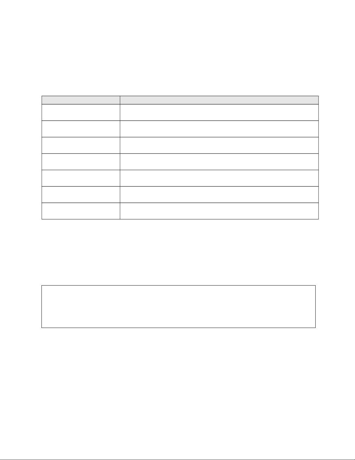
The Sample Gauges
Now that we’ve covered some of the basic constant and variable assignments for gauges, we’ll
move on to code for the sample gauges. This SDK includes sample code for the following
gauges.
Gauge Description
SDK.attitude.c
Attitude indicator, sprite example.
SDK.control_surfaces.c
Control Surfaces, slider example.
SDK.fuel.c
Fuel gauge, needle example.
SDK.fuel_selector.c
Fuel Selector, icon example.
SDK.temperature.c
Temperature gauge, string and icon examples.
SDK.wiskey.c
Whiskey Compass, moving image example.
SDK.FlightMap.c
Simple GPS-like gauge, example of implementing “owner draw”
gauges.
All of these files contain static image examples. The following sections describe the basic calls
made within a gauge source file, pointing out the individual distinctions for each gauge type.
Setting Up the Gauge Header
At the beginning of each sample gauge source file, you’ll see a code fragment like this:
// Set up gauge header
char attitude_gauge_name[] = GAUGE_NAME;
extern PELEMENT_HEADER attitude_list;
extern MOUSERECT attitude_mouse_rect[];
First, the code assigns values for the following variables used by the gauge header:
Attitude_gauge_name Identifies gauge name assigned in SDK.c
PELEMENT_HEADER Identifies which gauge macro forms the background
MOUSERECT Identifies mouse rectangle
26

Then the code fills in values for GAUGE_HEADER_FS700, the gauge header macro. The gauge
header is a structure that defines the interface used by the Panel system to control the gauge
DLL. You must export the gauge header to expose the gauge interface to the Panel system.
27
GAUGE_HEADER_FS700
Use the GAUGE_HEADER_FS700 macro to create and export the gauge header
(GAUGEHDR). The GAUGE_HEADER_FS700 macro creates GAUGEHDR, filling in the
unique members of the structure:
typedef struct GAUGEHDR
{
UINT32 gauge_header_version;
char *gauge_name;
PPELEMENT_HEADER elements_list;
PQUERY_ROUTINE query_routine;
PINSTALL_ROUTINE install_routine;
PINITIALIZE_ROUTINE initialize_routine;
PUPDATE_ROUTINE update_routine;
PGENERATE_ROUTINE generate_routine;
PDRAW_ROUTINE draw_routine;
PKILL_ROUTINE kill_routine;
char reserved_1[4];
UINT32 size_x_mm;
char reserved_2[40];
PMOUSERECT mouse_rect;
PGAUGE_CALLBACK gauge_callback;
UINT32 user_data;
PVOID parameters;
char* usage;
char reserved_3[16];
}
GAUGEHDR, *PGAUGEHDR, **PPGAUGEHDR;
The following example shows how to use the GAUGE_HEADER_FS700 macro in code:
GAUGE_HEADER_FS700(GAUGE_W, attitude_gauge_name, &attitude_list, \
attitude_mouse_rect, 0, 0, 0, 0);
Here’s the syntax for the GAUGE_HEADER_FS700 macro:
#define GAUGE_HEADER_FS700(default_size_mm, gauge_name, element_list,
pmouse_rect, pgauge_callback, user_data, parameters, usage)
28
The GAUGE_HEADER_FS700 macro has these members:
Member Description
default_size_mm The default X axis size of the gauge in design units. This value is set as
GAUGE_W in SDK.c.
gauge_name The name of the gauge as defined in SDK.c as GAUGE_NAME.
element_list A pointer to the first drawing element in the list of elements.
pmouse_rect A pointer to the mouse rectangle drawn over the gauge.
pgauge_callback A pointer to a function for the entire gauge. This will pass a message to the
system. Use 0 if none.
user_data A 32-bit space you can use for any data you want. Use 0 if none.
parameters A field that contains a string. A pointer to this string is placed in the gauge
header for use in the gauge callback function (or wherever might be
appropriate). Use 0 if none.
usage Not used. Use 0.
The GAUGE_HEADER_FS700 macro creates the GAUGEHDR structure and an exported
variable, gauge_header. The Panel system uses the gauge_header variable to initialize each of the
drawing elements. Most of the Panel API functions use gauge_header as one parameter to be
passed. You will use this variable often.
29
Simulating System Failures
Flight Simulator 2004 can simulate several types of aircraft system failures. Almost all of the
sample gauge source files contain code that illustrates how to set up a simulated system failure.
FAILURE_RECORD
You’ll use the FAILURE_RECORD structure to identify the systems that—should they fail—
would need to be reflected by the gauge. The structure inside Gauges.h looks like this:
typedef struct FAILURE_RECORD
{
FAILURE_KEY key;
FAILURE_ACTION action;
PENUM8 var;
}
FAILURE_RECORD, *PFAILURE_RECORD, **PPFAILURE_RECORD;
The following code illustrates how you can build FAILURE_RECORD for a Fuel gauge:
FAILURE_RECORD fuel_fail[] =
{
{FAIL_SYSTEM_ELECTRICAL_PANELS, FAIL_ACTION_ZERO},
{FAIL_GAUGE_FUEL_INDICATORS, FAIL_ACTION_FREEZE},
{FAIL_NONE, FAIL_ACTION_NONE}
This code creates a FAILURE_RECORD called fuel_fail.
Each FAILURE_KEY enum value identifies the system undergoing failure; its associated
FAILURE_ACTION identifies what happens in the event of that failure.
The final FAILURE_KEY and FAILURE_ACTION pair is always FAIL_NONE,
FAIL_ACTION_NONE.
30

Identifying the System Undergoing Failure
FAILURE_KEY
System failures are listed in the FAILURE_KEY enum values as shown below:
typedef enum FAILURE_KEY
{
FAIL_NONE = 0,
OLD_FAIL_SYSTEM_ELECTRICAL, // obsolete
FAIL_SYSTEM_ENGINE,
FAIL_SYSTEM_PITOT_STATIC,
FAIL_SYSTEM_VACUUM,
FAIL_GAUGE_ADF,
FAIL_GAUGE_AIRSPEED,
FAIL_GAUGE_ALTIMETER,
FAIL_GAUGE_ATTITUDE,
FAIL_GAUGE_COMMUNICATIONS,
FAIL_GAUGE_FUEL_INDICATORS,
FAIL_GAUGE_GYRO_HEADING,
FAIL_GAUGE_MAGNETIC_COMPASS,
FAIL_GAUGE_NAVIGATION, // this assumes no vors
FAIL_GAUGE_NAVIGATION_VOR1, // only vor1
FAIL_GAUGE_NAVIGATION_VOR2, // only vor2
FAIL_GAUGE_NAVIGATION_BOTH, // both vors
FAIL_GAUGE_TRANSPONDER,
FAIL_GAUGE_TURN_COORDINATOR,
FAIL_GAUGE_VERTICAL_SPEED,
FAIL_SYSTEM_ELECTRICAL_PANELS,
FAIL_SYSTEM_ELECTRICAL_AVIONICS,
FAIL_KEY_MAX
}
FAILURE_KEY, *PFAILURE_KEY, **PPFAILURE_KEY;
31
FAILURE_KEY
The following table describes the FAILURE_KEY enum values for Flight Simulator 2004.
Enum values Description
FAIL_NONE Marks the end of a failure record.
OLD_FAIL_SYSTEM_
ELECTRICAL
Is obsolete. Don’t use it in new FS2004 gauges;
use FAIL_SYSTEM_ELECTRICAL_PANELS
instead.
FAIL_SYSTEM_ENGINE Specifies an engine system failure.
FAIL_SYSTEM_PITOT_ STATIC Specifies a pitot-static system failure.
FAIL_SYSTEM_VACUUM Specifies a vacuum system failure.
FAIL_GAUGE_ADF Specifies an ADF gauge system failure.
FAIL_GAUGE_AIRSPEED Specifies an airspeed gauge system failure.
FAIL_GAUGE_ALTIMETER Specifies an altimeter gauge system failure.
FAIL_GAUGE_ATTITUDE Specifies an attitude gauge system failure.
FAIL_GAUGE_
COMMUNICATIONS
Specifies a communication gauge system failure.
FAIL_GAUGE_FUEL_
INDICATORS
Specifies a fuel indicators gauge system failure.
FAIL_GAUGE_GYRO_ HEADING Specifies a gyro heading gauge system failure.
FAIL_GAUGE_MAGNETIC_
COMPASS
Specifies a magnetic compass gauge system failure.
FAIL_GAUGE_NAVIGATION Specifies a navigation gauge system failure.
FAIL_GAUGE_NAVIGATION_
VOR1
Specifies a navigation VOR1 gauge system failure.
FAIL_GAUGE_NAVIGATION_
VOR2
Specifies a navigation VOR2 gauge system failure.
FAIL_GAUGE_NAVIGATION_
BOTH
Specifies a complete failure of the navigation radio.
32
FAIL_GAUGE_ TRANSPONDER Specifies a transponder gauge system failure.
FAIL_GAUGE_TURN_
COORDINATOR
Specifies a turn coordinator gauge system failure.
FAIL_GAUGE_VERTICAL_ SPEED Specifies a vertical speed indicator gauge system
failure.
FAIL_KEY_MAX Not used.
FAIL_SYSTEM_ELECTRICAL_
PANELS
Specifies a failure of the electrical panel.
FAIL_SYSTEM_ELECTRICAL_
AVIONICS
Specifies a failure of the electrical avionics.
33
Identifying the Failure Action
You can set up a gauge element to react to one or more of the system failures shown in the
FAILURE_RECORD by using one of the defined FAILURE_ACTION enum values:
typedef enum FAILURE_ACTION
{
FAIL_ACTION_NONE = 0,
FAIL_ACTION_FREEZE,
FAIL_ACTION_ZERO,
FAIL_ACTION_NO_DRAW,
FAIL_ACTION_COVER,
FAIL_ACTION_MAX
}
FAILURE_ACTION, *PFAILURE_ACTION, **PPFAILURE_ACTION;
FAIL_ACTION
The following table describes the FAIL_ACTION enum values for Flight Simulator 2004.
Member Description
FAIL_ACTION_NONE = 0 Takes no action. This type of failure record is typically used
as the background static image for covering a gauge.
FAIL_ACTION_FREEZE
Freezes the gauge element at its last updated position. The
element’s MODULE_VAR variable(s) will not be updated.
(MODULE_VAR relates to the various gauge token
variables accessible to the panel system from the simulation
engine. See the section on Token Variables for more
information.)
FAIL_ACTION_ZERO Sets the element MODULE_VAR variable(s) to 0.
FAIL_ACTION_NO_DRAW Erases the element and doesn't draw it again.
FAIL_ACTION_MAX Not used.
34
Using Gauge Macros
Moving a little further down in the sources for the various sample gauges, you’ll see different
macros being used to pass parameters between the gauge and the panel system. These macros are
defined in Gauges.h, and you can use them to create various types of gauges. Let’s continue
through the code to where macros first start appearing—we’ll look specifically at the sliders
example and then cover all the gauge macros in detail later on.
Sliders Example
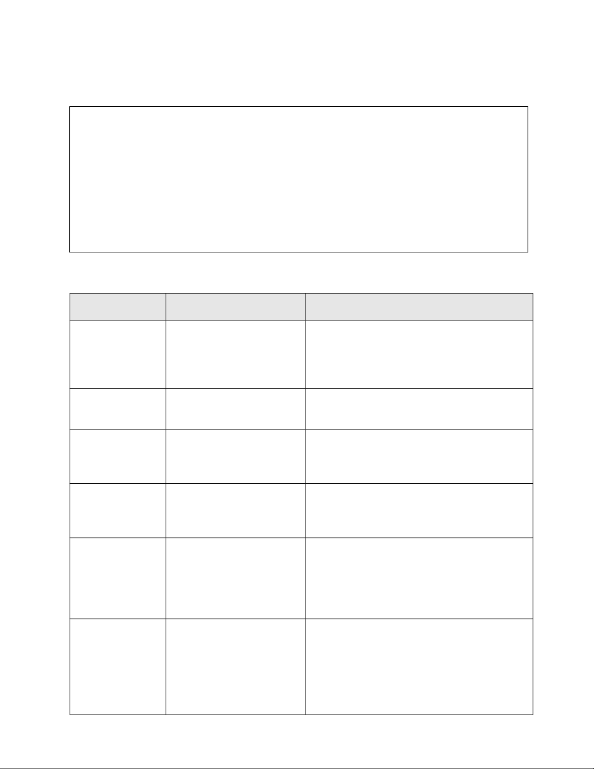
The SDK.control_surfaces.c example shows how to build a gauge using sliders that move over a
static image in the background. The code that follows uses the bitmaps listed in the table below
as resources:
Resource Bitmap Resource name Description
SDK.Control_Surfaces.Ailerons.BMP A slider (down pointer).
SDK.Control_Surfaces.Elevator.BMP A slider (left pointer).
SDK.Control_Surfaces.Rudder.BMP A slider (up pointer).
SDK.Control_Surfaces.Trim.BMP A slider (right pointer).
MAKE_SLIDER
The code first creates the sliders using the MAKE_SLIDER macro. Here’s the structure for the
MAKE_SLIDER macro from gauges.h:
#define MAKE_SLIDER( NAME, \
RES_ID, \
NEXT_LIST, \
FAILURE, \
DRAW_FLAGS, \
ASI_FLAGS, \
POSITION_X, POSITION_Y, \
SOURCE_VAR_X, CALLBACK_X, SCALE_X,\
SOURCE_VAR_Y, CALLBACK_Y, SCALE_Y )
35
You’ll need to fill this structure out with slider-specific information, such as the following from
SDK.Control_Surfaces.c:
MAKE_SLIDER
(
cs_slider_trim,
BMP_CS_SMALL_TRIM,
NULL,
0,
IMAGE_USE_ERASE | IMAGE_USE_TRANSPARENCY,
0,
20,44,
MODULE_VAR_NONE, NULL, 0,
ELEVATOR_TRIM, NULL, -100
)
The following table explains the different fields in MAKE_SLIDER.
Field Sample Code Description
NAME cs_slider_trim Contains the unique name you assign to the
macro—this specific name applies to the trim
slider. A gauge can have multiple sliders, but
each one must have a unique name
RES_ID BMP_CS_SMALL_TRIM Contains the name of the resource file used by
the slider as identified earlier by SDK.h.
NEXT_LIST NULL Sets the order in which parts of the gauge get
drawn. Set to NULL as this is a simple gauge
where the sliders do not overlap.
FAILURE 0 References the FAILURE_RECORD name
set earlier. Since this gauge doesn’t have one,
it’s set to 0.
DRAW_FLAGS IMAGE_USE_ERASE |
IMAGE_USE_
TRANSPARENCY
Defines how this slider bitmap appears on the
screen. You can combine multiple flags on the
same line separated by the | symbol. See
below for a list of all these flags and their
description.
ASI_FLAGS 0
Specifies whether to capture the current value
of the Altitude or Heading. This is a bitwise
field that Turns ON or OFF. If you set it to 0,
then Altitude and Heading will be manually
tunable. Valid entries are:
• ASI_ALT_MANUALLY_TUNABLE
• ASI_HEADING_MANUALLY_
36

TUNABLE
POSITION_X,
POSITION_Y
20,44 Specifies the X,Y coordinates, in display units
relative to the background image (i.e., static
image), at which to initially place the slider
bitmap.
37

SOURCE_VAR_X,
CALLBACK_X,
SCALE_X
MODULE_VAR_NONE
,
NULL,
0
Set the X-axis values. (You can move a slider
on the X or Y axis.).
• SOURCE_VAR_X identifies the token
variable the slider will use. Since Trim
goes only up and down, there’s no token
variable so use
MODULE_VAR_NONE.
• CALLBACK_X identifies the modifying
callback if any. None is needed, so set to
NULL.
• SCALE_X sets the scaling value for the
range of X-axis movement of the
variable across the background image.
Here it’s 0. A slider moves from left to
right unless this value is preceded by a
minus (-) sign.
SOURCE_VAR_Y,
CALLBACK_Y,
SCALE_Y
ELEVATOR_TRIM,
NULL,
-100
Set the Y-axis values. Here the Trim slider
does move on the Y-axis.
• SOURCE_VAR_Y uses the
ELEVATOR_TRIM token variable. For
more information, see the discussion of
token variables later in this section.
• CALLBACK_Y identifies the modifying
callback, which isn’t used here.
• SCALE_Y is the scaling value of the Y-
axis movement of the slider across the
background image. Divide the token
variable value returned by the range of
movement in pixels, and then multiply by
the units of measure. A slider moves from
top to bottom unless this value is
preceded by a minus (-) sign.
38
DRAW_FLAGS
The DRAW_FLAGS field is a combination of the following flags.
IMAGE_USE_TRANSPARENCY
This flag is used by C-style gauges for all element
types; it has nothing to do with the transparency of
a mask image used with an element. When black
(pure black, or an RGB value of 0,0,0) is anywhere
in a mask image, it is transparent, regardless of
whether or not this image flag is set.
IMAGE_USE_ERASE Use the access buffer for resource. Note: there is a
cost in memory and CPU usage.
IMAGE_USE_BRIGHT Use this to make the image appear lit at night.
IMAGE_NO_STATIC_BLENDING This is valid on static_images using
IMAGE_USE_TRANSPARENCY and first
element in list.
IMAGE_CONTAINS_MASK Image contains mask bits.
IMAGE_USE_ALPHA Image contains alpha channel.
IMAGE_USE_LUMINOUS Image is bright when the interior light is on.
IMAGE_USE_LUMINOUS_PARTIAL Parts of image are lit by interior light (alpha
channel).
IMAGE_HIDDEN Do not show this image until the gauge code
specifically calls for it. These change dynamically.
IMAGE_HIDDEN_TREE Do not show this image, and all images in the
resource tree above it, until the gauge code
specifically calls for it.
IMAGE_ON_SCREEN Status bit to say whether element is on the screen.
You force a gauge to re-plot by setting it off-screen.
The code in SDK.control_surfaces.c contains four separate MAKE_SLIDER macros, one for
each of the different sliders used.
PELEMENT_HEADER
After the final MAKE_SLIDER macro has been defined, you’ll see the following code:
PELEMENT_HEADER cs_sliders_list[] =
{
&cs_slider_trim.header,
39

&cs_slider_ailerons.header,
&cs_slider_elevator.header,
&cs_slider_rudder.header,
NULL
};
This PELEMENT_HEADER code signals the end of the series of macros and sets the order in
which these different parts of the gauge appear. The display order goes from top to bottom. This
works very well here since the various sliders do not overlap one another. Note that every macro
you define must have an associated PELEMENT_HEADER somewhere, and it must end with a
NULL.
The specific code fragment above sets the order for all sliders simultaneously. In cases where
sliders or other resources overlap, you could instead break these out separately. For example:
MAKE_SLIDER
(
cs_slider_ailerons,
BMP_CS_SMALL_AILERONS,
NULL,
0,
IMAGE_USE_ERASE | IMAGE_USE_TRANSPARENCY,
0,
95, 6,
AILERON_DEFLECTION, NULL, 100,
MODULE_VAR_NONE, NULL, 0
)
PELEMENT_HEADER cs_sliders_list1[] =
{
&cs_slider_ailerons.header,
NULL
}; \\ END OF FIRST SLIDER MACRO
MAKE_SLIDER(
cs_slider_elevator,
BMP_CS_SMALL_ELEVATOR,
&cs_sliders_list1,
0,
IMAGE_USE_ERASE | IMAGE_USE_TRANSPARENCY,
0,
98, 46,
MODULE_VAR_NONE, NULL, 0,
ELEVATOR_DEFLECTION, NULL, -70
)
PELEMENT_HEADER cs_sliders_list2[] =
{
&cs_slider_elevator.header,
NULL
}; \\ END OF SECOND SLIDER MACRO
MAKE_SLIDER
(
cs_slider_rudder,
BMP_CS_SMALL_RUDDER,
&cs_sliders_list2,
0,
IMAGE_USE_ERASE | IMAGE_USE_TRANSPARENCY,
0,
94, 83,
40

RUDDER_DEFLECTION, NULL, 80,
MODULE_VAR_NONE, NULL, 0
)
PELEMENT_HEADER cs_sliders_list3[] =
{
&cs_slider_rudder.header,
NULL
}; \\ END OF THIRD SLIDER MACRO
Note that the NEXT LIST parameter for the second slider references &cs_sliders_list1,
&cs_sliders_list2, and so forth, indicating the links between each MAKE_SLIDER instance.
41
Making the Background Image
To set the background image for the gauge, use the MAKE_STATIC macro. You will always
use this macro with every gauge you create. First, here’s the background resource used by
control_surfaces.c:
Resource Bitmap Resource name Description
SDK.Control_Surfaces.bg.BMP A static background against which
the sliders will move
up/down/left/right.
You’ll create the static background image with the MAKE_STATIC macro. As an example,
here’s the macro structure from Gauges.h:
#define MAKE_STATIC( NAME, \
RES_ID, \
NEXT_LIST, \
FAILURE, \
DRAW_FLAGS, \
ASI_FLAGS, \
POSITION_X, POSITION_Y ) \
And here’s the code fragment from Control_surfaces.c that uses MAKE_STATIC:
MAKE_STATIC
(
cs_background,
BMP_CS_SMALL_BACKGROUND,
&cs_sliders_list,
NULL,
IMAGE_USE_TRANSPARENCY,
0,
0,0
)
PELEMENT_HEADER cs_list = &cs_background.header;
42
The following table explains the different fields in MAKE_STATIC.
Field Sample Code Description
NAME cs_background Contains the unique name you assign to the macro
—this specific name applies to the static
background image.
RES_ID BMP_CS_SMALL_
BACKGROUND
Contains the name of the resource file used by the
slider as identified earlier by SDK.h.
NEXT_LIST &cs_sliders_list Sets the order in which parts of the gauge get
drawn. The example identifies the sliders.
FAILURE NULL References the FAILURE_RECORD name set
earlier. Since this gauge doesn’t have one, it’s set to
0.
DRAW_FLAGS IMAGE_USE_
TRANSPARENCY
Sets how the bitmap will display. These flags are
the same for all macros.
ASI_FLAGS 0
Specifies whether or not to capture the current
value of the Altitude or Heading. This is a bitwise
field that Turns ON or OFF. If you set it to 0, then
Altitude and Heading will be manually tunable.
Valid entries are:
• ASI_ALT_MANUALLY_TUNABLE
• ASI_HEADING_MANUALLY_TUNABLE
POSITION_X,
POSITION_Y
0,0 Specifies the X,Y coordinates, in display units
relative to the background image (i.e., static image),
at which to initially place the slider bitmap. Since
this is the background image, always set it to 0,0.
Finally, the PELEMENT_HEADER for the macro gets set to identify this image as the gauge
background:
PELEMENT_HEADER cs_list = &cs_background.header;
If you look back near the top of the code, you’ll see:
EXTERN PELEMENT_HEADER cs_list;
Here, the initial assignment of cs_list identifies this specific macro with the background image
for the gauge.
We’re pretty much nearing the end of our sample code inside the Control_surfaces.c file. Let’s
wrap up with a discussion of how to tell the mouse the gauge exists.
43
Defining Mouse Rectangles
By using mouse rectangles, you can specify how a gauge will interact with the mouse pointer
(i.e., mouse movement and mouse button clicks). For example, you can change the cursor or
display a ToolTip as the mouse enters the area you've defined as a mouse rectangle; you can also
trigger a Flight Simulator event or execute a callback function.
Note that the mouse rectangle you define is specific to the gauge itself—it works off the gauge
coordinates, not the panel background coordinates. This allows you to move the gauge around
the panel, while keeping the mouse rectangle intact.
To define a mouse rectangle, you use a combination of the mouse definition macros, as shown in
the following code example from the SDK.control_surfaces.c file:
MOUSE_BEGIN( cs_mouse_rect, HELP_NONE, 0, 0 )
MOUSE_PARENT( 0,0,44,94, HELPID_GAUGE_PITCH_TRIM)
MOUSE_PARENT( 60,0,76,16, HELPID_GAUGE_ROLL_TRIM)
MOUSE_PARENT( 82,16,32,62, HELPID_GAUGE_PITCH_TRIM)
MOUSE_PARENT( 60,78,76,16, HELPID_GAUGE_YAW_TRIM)
MOUSE_END
MOUSE_BEGIN, MOUSE_PARENT, and MOUSE_END are all macros you can use when
defining mouse rectangles. You should look inside the Gauges.h file to get a detailed
understanding of how these macros are defined.
MOUSE_BEGIN uses the following parameters.
Parameter Description
name Contains the name of the MOUSERECT you’ve assigned to the rectangle.
helpid Contains the Help ID of the ToolTip message you want to appear when a mouse
cursor enters the rectangle. For foreign versions, the Help IDs point to localized
strings. There is currently no way to add more ToolTip ID’s. For a complete list of
Help IDs, see the file HelpIDs.doc.
x, y Specifies the upper-left corner of the rectangle. For MOUSE_BEGIN, this value
will always be 0, 0.
MOUSE_END ends the definition of the rectangle. You can also create rectangles within
rectangles by using the capabilities of MOUSE_PARENT_* and MOUSE_CHILD_*.
44
Rectangles within Rectangles
You can also define sub-rectangles within the gauge rectangle using the MOUSE_PARENT and
MOUSE_PARENT_BEGIN macros. Both of these macros use the following parameters.
Parameter Description
x, y Specifies the X and Y position from the 0,0 position of the gauge.
w, h Specifies the width and height of the rectangle.
Help ID Specifies the Help ID of the ToolTip text to display for the rectangle. For
foreign versions, the Help IDs point to localized strings. There is currently no
way to add more ToolTip IDs. For a complete list of Help IDs, see the file
HelpIDs.doc.
The only difference between MOUSE_PARENT and MOUSE_PARENT_BEGIN is that
MOUSE_PARENT includes both MOUSE_PARENT_BEGIN and MOUSE_PARENT_END.
Generating Events
The MOUSE_CHILD_EVENT macro defines a sub-rectangle of the rectangle created by
MOUSE_PARENT_BEGIN. Using this macro, you can generate panel system events (such as
KEY_SMOKE_TOGGLE, which toggles the smoke system ON/OFF) from a mouse rectangle.
This macro uses the following syntax:
MOUSE_CHILD_EVENT(x, y, w, h, cursor, mouse_flags, event_id)
MOUSE_CHILD_EVENT uses the following parameters.
Parameter Description
x, y Specifies the upper-left corner of the rectangle.
w, h Specifies the width and height of rectangle.
Cursor
Specifies the cursor shown when the mouse is in the mouse rectangle.
This parameter can be set to one of the following:
• CURSOR_NONE
• CURSOR_NORMAL
• CURSOR_UPARROW
• CURSOR_DOWNARROW
• CURSOR_LEFTARROW
• CURSOR_RIGHTARROW
• CURSOR_HAND
• CURSOR_CROSSHAIR
45
mouse_flags
Specifies under what conditions the event will be generated. It can be set to one
of the following values:
• MOUSE_NONE
• MOUSE_RIGHTSINGLE
• MOUSE_MIDDLESINGLE
• MOUSE_LEFTSINGLE
• MOUSE_RIGHTDOUBLE
• MOUSE_MIDDLEDOUBLE
• MOUSE_LEFTDOUBLE
• MOUSE_RIGHTDRAG
• MOUSE_MIDDLEDRAG
• MOUSE_LEFTDRAG
• MOUSE_MOVE
• MOUSE_DOWN_REPEAT
• MOUSE_KEYBOARD
event_id Specifies the event to be sent to Flight Simulator 2004 by the mouse event. For
a complete list of events, see the associated file EventIDs.doc.
The following is an example of mouse rectangle setup code that generates the
KEY_FLAPS_DECR and KEY_FLAPS_INCR events:
MOUSE_BEGIN(mouse_rect, HELPID_B737_FLAPS, 0, 0)
MOUSE_CHILD_EVENT(0,0,44,85, CURSOR_DOWNARROW, MOUSE_LEFTSINGLE,
KEY_FLAPS_DECR)
MOUSE_CHILD_EVENT(44,0,44,85, CURSOR_UPARROW, MOUSE_LEFTSINGLE,
KEY_FLAPS_INCR)
MOUSE_END
46
Using Callback Functions
You can use the MOUSE_CHILD_FUNCT macro to specify a callback function when an event
specified by the mouse_flags parameter is triggered. You will need to define the callback
function with the mouse_child_funct function. The trigger_key_event and
panel_window_toggle functions are often used in the mouse event callback functions.
For specific information, see their descriptions in the Functions section below.
The syntax for MOUSE_CHILD_FUNCT is as follows:
MOUSE_CHILD_FUNCT(x, y, w, h, cursor, mouse_flags, function)
MOUSE_CHILD_FUNCT uses the following parameters:
Parameter Description
x, y Specifies the upper-left corner of the rectangle.
w, h Specifies the width and height of the rectangle.
cursor
Specifies the type of cursor that is shown when the mouse is in the mouse
rectangle. It can be set to one of the following:
• CURSOR_NONE
• CURSOR_NORMAL
• CURSOR_UPARROW
• CURSOR_DOWNARROW
• CURSOR_LEFTARROW
• CURSOR_RIGHTARROW
• CURSOR_HAND
• CURSOR_CROSSHAIR
mouse_flags
Specifies under what conditions the callback function will be executed. The
choices are:
• MOUSE_NONE
• MOUSE_RIGHTSINGLE
• MOUSE_MIDDLESINGLE
• MOUSE_LEFTSINGLE
• MOUSE_RIGHTDOUBLE
• MOUSE_MIDDLEDOUBLE
• MOUSE_LEFTDOUBLE
• MOUSE_RIGHTDRAG
• MOUSE_MIDDLEDRAG
• MOUSE_LEFTDRAG
• MOUSE_MOVE
• MOUSE_DOWN_REPEAT
• MOUSE_KEYBOARD
function Specifies the callback function executed by the mouse event. You must define
47

Here’s a code snippet showing how you’d use the MOUSE_CHILD_FUNCT macro to designate
a callback function:
MOUSE_BEGIN( fuel_selector_mouse_rect, HELPID_GAUGE_FUEL_SELECTOR, 0, 0 )
MOUSE_CHILD_FUNCT( 0,0,39,48, CURSOR_HAND, MOUSE_LEFTSINGLE,
fuel_selector_mouse_cb )
MOUSE_END
Creating Dynamic Mouse ToolTips
The SDK.FlightMap.c file contains the following code example of how you can use dynamic
ToolTips (i.e., ToolTips whose text changes depending on the state of the gauge):
MOUSE_TOOLTIP_TEXT_STRING (
"Ground Speed: %1!d! knots, Track: %2!d!°, Next Waypoint: %3!s!, Distance:
%4!.1f! nm", GPS_Args)
The first argument in MOUSE_TOOLTIP_TEXT_STRING above is the ToolTip text. Note that
changeable parts of the ToolTip text are specified by constructs such as “%1!d!”. These
constructs always start with a percent sign (“%”), followed by the argument number (in the
arguments array, GPS_Args). The argument number starts at 1 and increases sequentially. This
argument number is followed by a formatting argument. The formatting argument is placed
between exclamation marks (“!”), for example, !d!. This formatting argument is similar to the
arguments of the printf function (from the C Standard Library), where “d” (in the formatting
argument) prints an integer and “f” (in printf) prints a floating point number.
GPS_Args, in the code example above, is the name of the argument’s array. The code below,
taken from the sample file, illustrates how this array is defined.
MOUSE_TOOLTIP_ARGS (GPS_Args)
MOUSE_TOOLTIP_ARG (MODULE_VAR_NONE, 0, NULL, NULL, NULL,
GPSARG_Get_GroundSpeed, NULL, NULL)
MOUSE_TOOLTIP_ARG (MODULE_VAR_NONE, 0, NULL, NULL, NULL,
GPSARG_Get_Track, NULL, NULL)
MOUSE_TOOLTIP_ARG (MODULE_VAR_NONE, 0, NULL, NULL, NULL, NULL, NULL,
GPSARG_Get_WP_ID)
MOUSE_TOOLTIP_ARG (MODULE_VAR_NONE, 0, NULL, NULL, NULL,
GPSARG_Get_WP_Distance, NULL, NULL)
MOUSE_TOOLTIP_ARGS_END
49

Arguments in the MOUSE_TOOLTIP_ARG macro follow this order:
• First, the MODULE_VAR enum, which defines a module variable from which to get the
value.
• Second, the scaling number, i.e., the numeric value of the module variable to be multiplied
by.
• Next, pointers to three different lookup tables. If you don’t want to use them, just use NULL
pointers.
• Finally, the pointer to callback functions.
All functions have the same argument but have a return result of different types. The arguments
are:
• The numeric value of the module variable after scaling and lookup in the numeric lookup
table.
• The id, which is the value from the id lookup table.
• A string pointer, from the string lookup table.
• The pointer to the MODULE_VAR structure initialized to the first argument of the
MOUSE_TOOLTIP_ARG macro.
• The pointer to the gauge header.
These functions can return: a numeric value, used together with numeric formats “d” or “f”; the
id value used as a HELPID enum by Flight Simulator; or a string value used with “s” format. For
details, see the SDK.FlightMap.c example.
Compiling and Using Your Gauges
Once you’ve finished defining the mouse rectangle(s) for your gauges, you can compile the files
and start the process of testing, debugging, and rebuilding—until you wind up with gauges
you’re happy with. You can create gauges using the Visual C++ compiler, version 4.0 or later.
The process used for compiling gauges with other compilers should be similar.
To compile and view your new gauges, complete these steps:
1. Before you start compiling your files, make sure your Visual C++ environment variables and
paths are set up correctly.
2. Change to the sample directory (\sample) and type nmake. This will build the Sdk.gau file,
which includes six different gauges you can place on a single panel.
3. Copy Sdk.gau to your \Flight Simulator 9\Gauges directory.
50

4. Make sure you have the Panel.cfg file properly set up with the gauges positioned where you
want them.
5. Make sure you have your aircraft’s Container system properly configured, i.e., pointing to
the right .air file, panel folder, etc.
6. Start Flight Simulator 2004, load your aircraft, and check out your new panel.
51
Using Token Variables
Gauges have access to information about the Flight Simulator simulation state. You can access
state information through a set of token variables. A complete list of token variables is available
in the file TokenVar.doc in this SDK.
The state information provided to the token variables depends on the aircraft’s .air file. Each .air
file that ships with Flight Simulator 2004 provides access to different token variables. For
example, the Cessna 182 provides access to GROUND_ALTITUDE, as does every other
aircraft. The Cessna 182, however, doesn’t provide access to the
TURB_ENGINE_1_VIBRATION variable because the Cessna 182’s .air file specifies that this
aircraft has a reciprocating engine, not a turbine engine.
Therefore, it’s important to make sure that the .air file you’re using for your aircraft and gauges
supports the token variables those gauges require.
UNIVERSAL_VAR Types
Each token variable returns a specific type of data. The following structure shows how the
UNIVERSAL_VAR variable is defined and the types that could be returned:
typedef union UNIVERSAL_VAR {
FLOAT64 n;'You can use any number.
BOOL b;// any boolean
ENUM e;// any enumerated value
FLAGS f;// any flags field
PVOID p;// any pointer
VAR32 d;// any binary coded decimal
VAR32 o;// any binary coded octal
} UNIVERSAL_VAR, *PUNIVERSAL_VAR, **PPUNIVERSAL_VAR;
For a table of available module variables, see the file TokenVar.doc. The table lists the module
variable name and description. It also specifies which UNIVERSAL_VAR union member to use
with each variable.
Accessing Token Variables
You can access token variables in three ways:
• From various Gauge macros as described earlier.
• Through drawing elements. In the element structure, you can specify which variable controls
the element. For example, you may have a needle (ELEMENT_NEEDLE) that is controlled
by the variable VERTICAL_SPEED. As the needle is updated, it will refer to the variable
VERTICAL_SPEED to determine the angle at which it will be displayed. For details, see the
section Using Drawing Elements in this document.
• Through the Panel API. For more information, see the following procedure.
52
To access a tokenized variable through the Panel API
1. Instantiate a MODULE_VAR variable initializing the GAUGE_TOKEN ID structure
member. You can set the ID to one of the token variables provided in the file TokenVar.doc.
For example:
typedef struct MODULE_VAR
{
GAUGE_TOKEN id;
PVOID var_ptr;
VAR_TYPE var_type;
UNIVERSAL_VAR var_value;
UNIVERSAL_VAR var_old;
} MODULE_VAR, *PMODULE_VAR, **PPMODULE_VAR;
2. To update the contents of the variable from Flight Simulator 2004 state information, use
lookup_var:
lookup_var(PMODULE_VAR module_var )
After the lookup_var function is called, the value of a MODULE_VAR variable is stored in the
var_value member of the structure.
Important: Token variables are read-only. Any attempt to set these variables through the
var_ptr variable may result in program crashes and incompatibility with future versions of
Flight Simulator.
The following code example shows how the MODULE_VAR variable is used. Note that this is a
callback function and, in this specific example, it is for a sprite element.
MODULE_VAR attitude_bank = { ATTITUDE_INDICATOR_BANK_DEGREES };
FLOAT64 flight_director_bank_cb( PELEMENT_SPRITE pelement )
{
lookup_var(&attitude_bank);
// Offset by attitude card's bank
return attitude_bank.var_value.n - pelement->source_var_0.var_value.n;
}
53
Gauge Macros and Drawing Elements
Each of the Gauge macros makes use of the drawing elements available in Flight Simulator
2004. These drawing elements are part of the macro definition in Gauges.h. Here’s each macro
and its associated element.
Macro Drawing Element
MAKE_STATIC ELEMENT_STATIC_IMAGE
MAKE_NEEDLE ELEMENT_NEEDLE
MAKE_STRING ELEMENT_STRING
MAKE_SLIDER ELEMENT_SLIDER
MAKE_ICON ELEMENT_ICON
MAKE_MOVING ELEMENT_MOVING_IMAGE
MAKE_SPRITE ELEMENT_SPRITE
Shared Data Elements
Each macro has twelve shared data elements, which aren't included in the declaration of each
structure. Instead, a #define HEADER is present that, when expanded, produces the twelve data
members. The following code examples show the drawing element ELEMENT_NEEDLE before
and after expansion.
Before expansion:
typedef struct ELEMENT_NEEDLE
{
HEADER;
'Needle-specific data members
};
After expansion:
typedef struct ELEMENT_NEEDLE
{
ELEMENT_TYPE_ENUM element_type;
ID resource_id;
PIXPOINT position;
PIXPOINT previous_position;
PIXPOINT ofs;
PGAUGEHDR gauge_header;
struct ELEMENT_HEADER previous_element;
54

struct ELEMENT_HEADER next_element;
PFAILURE_RECORD failure_systems;
FLAGS image_flags;
FLAGS aircraft_special_instrumentation;
FLAGS reserved;
'Needle-specific data members.
};
55
Drawing Element Header
The first twelve data members are the same for all the drawing element structures. The data
members are described in the following table.
Member Description
element_type
Specifies the element type. Set this member to be one of the following
elements:
• ELEMENT_TYPE_STATIC_IMAGE
• ELEMENT_TYPE_NEEDLE
• ELEMENT_TYPE_STRING
• ELEMENT_TYPE_SLIDER
• ELEMENT_TYPE_ICON
• ELEMENT_TYPE_MOVING_IMAGE
• ELEMENT_TYPE_SPRITE
resource_id Specifies the resource ID of an 8-bit or 24-bit bitmap resource. All
element types, with the exception of ELEMENT_STRING (which ignores
this value), use this value.
position Specifies the point that the drawing element pivots around. This value is
used by ELEMENT_NEEDLE and ELEMENT_SPRITE and ignored by
the other elements.
previous_position Specifies the previous position of the element relative to the gauge
position. Used by the Panel system. This value is ignored during
initialization.
ofs Specifies an offset (pivot point) for an element to rotate around. This
value is used by ELEMENT_NEEDLE and ELEMENT_SPRITE and
ignored by the other elements.
gauge_header Points to the gauge header file.
previous_element Points to the previous element. This value is set by the Panel system. This
value is ignored during initialization.
next_element Points to a list of graphical elements. The elements are drawn after the
current element. This value is used to determine the drawing order of all
the elements in your gauge.
failure_systems Points to a FAILURE_RECORD list. This list defines how an element
will react during simulated aircraft system failure.
56
image_flags
Specifies how the element image will be rendered. This member can be a
combination of the following values:
• IMAGE_USE_TRANSPARENCY - Renders the image using
transparency. If this flag is set, RGB color (0,0,0) is treated as
transparent in a 24-bit bitmap. Because non-transparent rendering is
faster than transparent rendering, you can use this flag to enhance
performance.
• IMAGE_USE_ERASE - Before the graphical element is rendered, a
"snapshot" of the background is saved. As a result, the Panel system
can erase the element as needed by plotting the contents of the save
buffer to the screen. You can use this flag to increase performance and
save memory if an element never needs to be erased. Static images use
this flag extensively.
• IMAGE_USE_BRIGHT - Maps the element’s image colors to the
section of the Flight Simulator 2004 palette that doesn't change during
the transition from day to night. The image colors will not change.
• IMAGE_NO_STATIC_BLENDING - This flag is only valid on static
images using IMAGE_USE_TRANSPARENCY and the first element
in the list.
• IMAGE_USE_ALPHA – The image contains alpha channel.
• IMAGE_USE_LUMINOUS – The image is bright when the interior
light is on.
• IMAGE_USE_LUMINOUS_PARTIAL - Parts of the image are lit by
interior light (alpha channel).
• IMAGE_HIDDEN_TREE - You can set this flag dynamically to hide
or show the element and all elements in the resource tree above it.
• IMAGE_HIDDEN - You can set this flag dynamically to hide or
show the element.
aircraft_special_
instrumentation
Specifies how the element will react in a special instrument situation.
Currently this is used only with autopilot. This member can have the
following values:
• ASI_ALT_MANUALLY_TUNABLE - Sets a global flag that causes
Flight Simulator 2004 to recognize that autopilot altitude hold is
manually tunable. If this flag isn't set, turning on altitude hold
maintains the current altitude instead of the currently set altitude.
• ASI_HEADING_MANUALLY_TUNABLE
Sets a global flag that causes Flight Simulator 2004 to recognize that
autopilot heading hold is manually tunable. If this flag isn't set, turning
on heading hold would maintain the current heading instead of the
currently set heading.
reserved This value is reserved and must be set to 0.
57

Drawing Element Structures
Each drawing element structure has one or more MODULE_VAR members. You can initialize
these members to one of the token variable values. Call the function element_install or
element_list_install to initialize the MODULE_VAR element(s).
The element_update or element_list_update function can be used to update the contents of the
MODULE_VAR. The elements themselves use the MODULE_VAR information at render time
to determine in what state they'll be rendered.
Graphical elements can use the MODULE_VAR structure member to determine the state in
which the element will be rendered. Sometimes, however, MODULE_VAR may not be a useful
value. You can get around this problem by using callbacks. For each of the MODULE_VAR
structures listed in the element structure, you can set an associated PMODULE_VAR_CB
pointer. The pointer points to a callback function that you can use to set the variable to a useful
value. The callback function is called by the Panel system after the variable has been updated
from the simulation state information. The callback function is generally used to normalize or
scale the MODULE_VAR value into a valid range. You can also use the callback function to
convert enumerated values, interpret a flag's variable, and so on.
For example, the following code uses a callback routine to clip the airspeed to a useful range that
can be used by the airspeed gauge. All elements use the same style callback routine in which the
argument to the function acts as a pointer to that element.
FLOAT64 convert_var_aspeed(PMODULE_VAR var)
{
if (var->var_value.n > GAUGE_MAX_AIRSPEED)
var->var_value.n = GAUGE_MAX_AIRSPEED;
if (var->var_value.n < 60)
var->var_value.n = 60;
return var->var_value.n;
}
You can set any callback pointer to NULL so that no call will occur.
NOTE: Any assignments to the MODULE_VAR in a callback routine are discarded. The final
value set in MODULE_VAR is the return value of the callback function.
58
Drawing Element Lists
In code, the drawing elements are organized (using the next_element data member) in a tree
structure (the element list). This element list defines the drawing order of the gauge elements:
• The first element in the list in the gauge header is drawn first.
• Each subsequent element in the list is drawn in the order it appears in the list.
• Before drawing the next element in the list, the current element’s element-list pointer is
examined. If the pointer is not NULL, the element’s element list is drawn using the same
logic.
You don't need to set the previous_element pointer. This pointer is initialized by the Panel
system when the gauge is initialized.
Gauge Macro Reference
This section describes each of the following gauge macros:
• MAKE_STATIC
• MAKE_NEEDLE
• MAKE_STRING
• MAKE_SLIDER
• MAKE_ICON
• MAKE_MOVING
• MAKE_SPRITE
MAKE_STATIC
The MAKE_STATIC macro draws the simplest type of graphical element. Use MAKE_STATIC
to draw an image that never changes.
Here’s the macro structure from Gauges.h:
#define MAKE_STATIC( NAME, \
RES_ID, \
NEXT_LIST, \
FAILURE, \
DRAW_FLAGS, \
ASI_FLAGS, \
POSITION_X, POSITION_Y ) \
59
And here’s the code fragment from Control_surfaces.c that uses MAKE_STATIC:
MAKE_STATIC
(
cs_background,
BMP_CS_SMALL_BACKGROUND,
&cs_sliders_list,
NULL,
IMAGE_USE_TRANSPARENCY,
0,
0,0
)
PELEMENT_HEADER cs_list = &cs_background.header;
The following table explains the different fields in MAKE_STATIC.
Field Sample Code Description
NAME cs_background Contains the unique name you assign to the
macro—this specific name applies to the static
background image.
RES_ID BMP_CS_SMALL_
BACKGROUND
Contains the name of the resource file used by the
macro as identified earlier by SDK.h.
NEXT_LIST &cs_sliders_list Sets the order in which parts of the gauge get
drawn. The example identifies the sliders.
FAILURE NULL References the FAILURE_RECORD name set
earlier. Since this gauge doesn’t have one, it’s set
to 0.
DRAW_FLAGS IMAGE_USE_
TRANSPARENCY
Sets how the bitmap will display. These flags are
the same for all macros.
ASI_FLAGS 0
Specifies whether to capture the current value of
the Altitude or Heading. This is a bitwise field
that Turns ON or OFF. If you set this field to 0,
Altitude and Heading will be manually tunable.
Valid entries are:
• ASI_ALT_MANUALLY_TUNABLE
• ASI_HEADING_MANUALLY_TUNABLE
POSITION_X,
POSITION_Y
0,0 Specifies the X,Y coordinates, in display units
relative to the background image (i.e., static
image), at which to initially place the bitmap.
Since this is the background image, always set the
X,Y coordinates to 0,0.
60

61
MAKE_NEEDLE
Use MAKE_NEEDLE to draw an image that pivots around a specific point in another image.
MAKE_NEEDLE supports transparency and nonlinear gauges. For MAKE_NEEDLE, POS
(position) is the center of rotation in the background image; OFS (offset) is the center of rotation
in the needle image.
Here’s the macro structure from Gauges.h:
#define MAKE_NEEDLE( NAME, \
RES_ID, \
NEXT_LIST, \
FAILURE, \
DRAW_FLAGS, \
ASI_FLAGS, \
BKND_POSITION_X, BKND_POSITION_Y, \
NDL_POSITION_X, NDL_POSITION_Y, \
SOURCE_VAR, CALLBACK, \
NONLINEARITY_TABLE, \
MAX_DEG_PER_SEC ) \
And here’s the code fragment from SDK.fuel.c that uses this macro:
MAKE_NEEDLE
(
fuel_needle,
BMP_FUEL_SMALL_NEEDLE,
NULL,
fuel_fail,
IMAGE_USE_TRANSPARENCY | IMAGE_USE_ERASE,
0,
150, 150,
6, 12,
FUEL_QUANTITY_CENTER,fuel_needle_cb,
fuel_nonlinearity,
6
)
The following table explains the different fields in MAKE_NEEDLE.
Field Sample Code Description
NAME fuel_needle Contains the unique name you assign to
the macro—this specific name applies to
the static background image.
RES_ID BMP_FUEL_SMALL_
NEEDLE
Contains the name of the resource file
used by the needle as identified earlier
by SDK.h.
NEXT_LIST NULL Sets the order in which parts of the
62

gauge get drawn.
FAILURE fuel_fail References the FAILURE_RECORD
name set earlier.
63
DRAW_FLAGS IMAGE_USE_
TRANSPARENCY |
IMAGE_USE_ERASE
Sets how the bitmap will display. These
flags are the same for all macros.
ASI_FLAGS 0
Specifies whether to capture the current
value of the Altitude or Heading. This is
a bitwise field that Turns ON or OFF. If
you set it to 0, then Altitude and
Heading will be manually tunable. Valid
entries are:
• ASI_ALT_MANUALLY_
TUNABLE
• ASI_HEADING_MANUALLY_
TUNABLE
BKND_POSITION_X,
BKND_POSITION_Y
150, 150 The X and Y coordinates on the
background image around which the
needle rotates.
NDL_POSITION_X,
NDL_POSITION_Y
6, 12 The X and Y coordinates of the needle
itself around which the needle revolves
—the fix point of the needle. In general,
bitmaps for needles should be drawn
horizontally.
SOURCE_VAR FUEL_QUANTITY_
CENTER
Token Variable used to drive the needle.
You can enter MODULE_VAR_NONE
if you want to set your variable values.
CALLBACK fuel_needle_cb Callback function associated with the
needle.
NONLINEARITY_
TABLE
fuel_nonlinearity Name of the non-linearity table used by
the needle. See the discussion below on
non-linearity tables.
MAX_DEG_PER_SEC 6 Determines the refresh rate for the
macro. Gauges are refreshed 18 times
per second, so a value of 0 means update
every cycle; a value of 6 means update
every third of a second. You trade off
gauge display quality versus frame rate
—lower numbers give smoother display
but worse frame rate.
64
Using Non-Linearity Tables
In some cases, you might want a needle to move in a nonlinear manner. For example, an airspeed
gauge sometimes shows a greater angle between 0 and 50 knots than the angle between 100 and
150 knots. You can specify this behavior by using a non-linearity table.
A non-linearity table is an array of NONLINEARITY structures. Each element in the array
represents a discrete point on a gauge where the value is known. For example, your gauge might
show airspeed as values from 0 to 160 knots, with tick marks every 20 knots. You could create
an entry for each tick, filling in the pt and value member variables of the NONLINEARITY
structure.
A NONLINEARITY structure uses the following members.
Member Description
pt Specifies the X, Y point in the background bitmap.
value Contains the readout of the gauge at that point.
degrees Used internally by the Panel system: do not use. Must be set to 0.
In SDK.Fuel.c, the linearity table deals with the fuel quantity, which ranges from 0 to 75. Here’s
the non-linearity table it uses:
NONLINEARITY fuel_nonlinearity[] =
{
{{30, 182}, 0, 0},
{{119, 47}, 25, 0},
{{246, 93}, 50, 0},
{{241, 221}, 75, 0}
};
At runtime, the value of the needle is examined and the angle to be drawn is interpolated from
the non-linearity table.
Values are listed in the table as they appear on the gauge (clockwise around the face). If gauge
values increase when rotating clockwise, values in the non-linearity table will start at the
minimum and increase. If gauge values decrease when rotating clockwise, then values in the
table will start with the maximum and decrease.
65

MAKE_STRING
Use MAKE_STRING to display text on a gauge. MAKE_STRING is particularly useful when
you have a string that changes as the gauge is updated; the string can be automatically updated
by setting up the MODULE_VAR elements and using callback functions. Using
MAKE_STRING, you can specify the font name, weight, and the background and foreground
colors of the text. You can also specify a highlight text color to use when the string is selected.
Here’s the macro structure from Gauges.h:
#define MAKE_STRING( NAME, \
NEXT_LIST, \
FAILURE, \
DRAW_FLAGS, \
ASI_FLAGS, \
POSITION_X, POSITION_Y, \
SIZE_X, SIZE_Y, \
NUM_CHARS, \
SOURCE_VAR_1, \
SOURCE_VAR_2, \
SOURCE_VAR_3, \
FORECOLOR, \
BACKCOLOR, \
HILITECOLOR, \
FONT_NAME, \
FONT_WEIGHT, \
FONT_CHARSET, \
FONT_SIZE, \
DRAW_TEXT_FLAGS, \
HILITE_LIST, \
CALLBACK) \
Here’s the code fragment from SDK.Temperature.c that uses the MAKE_STRING macro:
MAKE_STRING
(
temperature_string,
NULL,
temperature_fail,
IMAGE_USE_ERASE | IMAGE_USE_BRIGHT,
0,
28, 9,
60, 29,
3,
TOTAL_AIR_TEMP,
DISPLAY_UNITS,
MODULE_VAR_NONE,
RGB(255,0,0),
RGB(0,0,0),
RGB(92,92,92),
GAUGE_FONT_DEFAULT,
GAUGE_WEIGHT_DEFAULT,
GAUGE_CHARSET,
0,
DT_CENTER | DT_VCENTER | DT_SINGLELINE,
NULL,
temperature_string_cb
)
66
The following table explains the different fields in MAKE_STRING.
Field Sample Code Description
NAME temperature_string Contains the unique name you assign to
the macro—this specific name applies to
the static background image.
RES_ID NULL Contains the name of the resource file
used by the macro.
NEXT_LIST NULL Sets the order in which parts of the
gauge are drawn.
FAILURE temperature_fail References the FAILURE_RECORD
name set earlier.
DRAW_FLAGS IMAGE_USE_ERASE |
IMAGE_USE_BRIGHT
Sets how the bitmap will display. These
flags are the same for all macros.
ASI_FLAGS 0
Specifies whether to capture the current
value of the Altitude or Heading. This is
a bitwise field that Turns ON or OFF. If
you set it to 0, Altitude and Heading will
be manually tunable. Valid entries are:
• ASI_ALT_MANUALLY_
TUNABLE
• ASI_HEADING_MANUALLY_
TUNABLE.
POSITION_X,
POSITION_Y
28, 9 Specifies the X and Y coordinates on the
background image where you want the
text to display.
SIZE_X, SIZE_Y 60, 29 Defines the height and width of each
character.
NUMCHARS 3 Specifies the number of characters to
use in the string. The optimal font size is
calculated using the information passed
to the macro.
SOURCE_VAR_1 Contains the token variable used to
update the string. The string can contain
numbers, characters, or both. If you
want to set your variable values, enter
MODULE_VAR_NONE.
67
SOURCE_VAR_2 DISPLAY_UNITS Used to look up multiple token variables
to update the string. (e.g., Hours,
Minutes, Seconds). Sequence them
inside the callback function.
SOURCE_VAR_3 MODULE_VAR_NONE Contains the token variable used to
update the string.
FORECOLOR RGB(255,0,0), Defines the foreground (or daylight)
color of the string display.
68
BACKCOLOR RGB(0,0,0), Defines the background color of the
string display.
HILITECOLOR RGB(92,92,92), Defines the highlight color for the
selected area.
FONT_NAME GAUGE_FONT_
DEFAULT
Contains the font name of the string. For
more information, see “Defining the
Font Type” below.
FONT_WEIGHT GAUGE_WEIGHT_
DEFAULT
Contains the font weight of the string.
(The sample code sets the value of
GAUGE_WEIGHT_DEFAULT to
FW_NORMAL.)
Specifies the weight of the font in the
range 0 through 1000. For example, 400
is normal and 700 is bold. If this value is
zero, a default weight is used.
The following values are defined for
convenience.
Value Weight
FW_DONTCARE 0
FW_THIN 100
FW_EXTRALIGHT 200
FW_ULTRALIGHT 200
FW_LIGHT 300
FW_NORMAL 400
FW_REGULAR 400
FW_MEDIUM 500
FW_SEMIBOLD 600
FW_DEMIBOLD 600
FW_BOLD 700
FW_EXTRABOLD 800
FW_ULTRABOLD 800
FW_HEAVY 900
FW_BLACK 900
69
FONT_CHARSET GAUGE_CHARSET Specifies the font character set for the
string. A list of valid values can be
found in the CreateFont Win32 API.
FONT_SIZE 0 Specifies the font size for the string. A
value of zero (0) means scale so that
NUMCHARS capital W's fit into
SIZE_X. A non-zero FONT_SIZE
means fixed height.
70
DRAW_TEXT_
FLAGS
DT_CENTER |
DT_VCENTER |
DT_SINGLELINE
Sets how to draw the text. There are
three valid entries:
• DT_CENTER
• DT_VCENTER
• DT_SINGLELINE
HILITE_LIST NULL Lists gauge selection states. For a table
listing all gauge selection states, see
“Selecting a String by KEY_EVENT”
below. (You can also find examples of
gauge selection states in Gauges.h.)
CALLBACK temperature_string_cb Updates the string. The callback
function updates the string member
variable. The string member variable is
the character string data that's used to
render this drawing element.
71

Defining the Font Type
To define the font type you must place #define statements (after the initial #include) in your
gauge code. For example, SDK.Temperature.c looks like this:
#define GAUGE_CHARSET DEFAULT_CHARSET
#define GAUGE_FONT_DEFAULT "Courier New"
#define GAUGE_WEIGHT_DEFAULT FW_NORMAL
The first line in the code above is the default character set for English (UK and US). Most
instruments are labeled in English.
The second line defines the font set name. You want to define a font that will, with almost
certainty, exist on your user’s PC. Therefore, choose one of the following fonts: Courier New,
Arial, Times New Roman, or Helvetica.
The third line defines how the font will display. Here are the available options:
• FW_THINFW_EXTRALIGHT
• FW_LIGHT
• FW_NORMAL
• FW_MEDIUM
• FW_SEMIBOLD
• FW_BOLD
• FW_EXTRABOLD
• FW_HEAVY
72
Selecting a String by KEY_EVENT
You can use the SEQ_REC table to select a string automatically on certain KEY_EVENTs.
Flight Simulator 2004 allows the user to select certain gauge elements by using different
keyboard combinations. The SEQ_REC structure sets up the relationship between the current
selection state and the characters that can be selected for that state. The following code example
shows the SEQ_REC structure definition:
typedef struct SEQ_REC
{
int seq_id;
int sel_str;
int sel_end;
} SEQ_REC, *PSEQ_REC, **PPSEQ_REC;
SEQ_REQ uses the following members.
Member Description
seq_id Specifies the selection state.
sel_str Specifies the first character to select when the Flight Simulator 2004 selection state is
equal to the seq_id state.
sel_end Specifies the last character to select.
To mark the end of the array you must add one blank record that sets seq_id, sel_str, and
sel_end to SELECT_NONE, 0, and 0, respectively. The following code example shows a sample
SEQ_REC definition:
SEQ_REC seq_com[] =
{
{SELECT_COM_WHOLE, 0, 2},
{SELECT_COM_FRACTION, 4, 5},
{SELECT_NONE, 0, 0}
};
The following table includes the gauge selection states available in Flight Simulator 2004.
SEQ Record ID Description
SELECT_NONE No selection
SELECT_1 Unused
SELECT_ZOOM Zoom
SELECT_MAGNETO Magneto
73
SELECT_COM_WHOLE Communication frequency, whole number
SELECT_COM_FRACTION Communication frequency, fractional number
SELECT_NAV1_WHOLE Navigation radio frequency #1, whole number
SELECT_NAV1_FRACTION Navigation radio frequency #1, fractional number
SELECT_NAV2_WHOLE Navigation radio frequency #2, whole number
SELECT_NAV2_FRACTION Navigation radio frequency #2, fractional number
SELECT_XPNDR_1000 Transponder frequency fourth digit
SELECT_XPNDR_0100 Transponder frequency third digit
SELECT_XPNDR_0010 Transponder frequency second digit
SELECT_XPNDR_0001 Transponder frequency first digit
SELECT_VOR1 Toggle to VOR1 selection
SELECT_VOR2 Toggle to VOR2 selection
SELECT_ENGINE Toggle engine selection
SELECT_DME1 Toggle to DME1 selection
SELECT_DME2 Toggle to DME2 selection
SELECT_ADF_100 ADF frequency third digit
SELECT_ADF_010 ADF frequency second digit
SELECT_ADF_001 ADF frequency first digit
SELECT_EGT_BUG EGT bug
SELECT_SIM_RATE Simulation rate
SELECT_CLOCK_HOURS Clock hours
SELECT_CLOCK_MINUTES Clock minutes
SELECT_CLOCK_SECONDS Clock seconds
SELECT_STANDBY_ Standby communication frequency, whole number. No
74
COM_WHOLE standby frequencies are implemented.
SELECT_STANDBY_
COM_FRACTION
Standby communication frequency, fractional number. No
standby frequencies are implemented.
SELECT_STANDBY_
NAV_WHOLE
Standby navigation radio frequency, whole number. No
standby frequencies are implemented.
SELECT_STANDBY_NAV_
FRACTION
Standby navigation radio frequency, fractional number. No
standby frequencies are implemented.
SELECT_STANDBY_ ADF_100 Standby ADF frequency, third digit. No standby
frequencies are implemented.
SELECT_STANDBY_ ADF_010 Standby ADF frequency, second digit. No standby
frequencies are implemented.
SELECT_STANDBY_ ADF_001 Standby ADF frequency, first digit. No standby
frequencies are implemented.
75
MAKE_SLIDER
Use MAKE_SLIDER to move a drawing element around a gauge on the X and Y axes.
You can use MAKE_SLIDER to move an image in only one direction as well. Just set the
MODULE_VAR, for either X or Y, to MODULE_VAR_NONE.
Here’s the macro structure from Gauges.h:
#define MAKE_SLIDER( NAME, \
RES_ID, \
NEXT_LIST, \
FAILURE, \
DRAW_FLAGS, \
ASI_FLAGS, \
POSITION_X, POSITION_Y, \
SOURCE_VAR_X, CALLBACK_X, SCALE_X, \
SOURCE_VAR_Y, CALLBACK_Y, SCALE_Y )
You’ll need to fill this structure out with slider-specific information, such as the following from
SDK.Control_Surfaces.c:
MAKE_SLIDER
(
cs_slider_trim,
BMP_CS_SMALL_TRIM,
NULL,
0,
IMAGE_USE_ERASE | IMAGE_USE_TRANSPARENCY,
0,
20,44,
MODULE_VAR_NONE, NULL, 0,
ELEVATOR_TRIM, NULL, -100
)
76
The following table explains the different fields in MAKE_SLIDER.
Field Sample Code Description
NAME cs_slider_trim Contains the unique name you assign
to the macro—this specific name
applies to the trim slider. A gauge can
have multiple sliders, but each one
must have a unique name
RES_ID BMP_CS_SMAL
L_TRIM
Contains the name of the resource file
used by the slider as identified earlier
by SDK.h.
NEXT_LIST NULL Sets the order in which parts of the
gauge get drawn. Set to NULL as this
is a simple gauge where the sliders do
not overlap.
FAILURE 0 References the FAILURE_RECORD
name set earlier. Since this gauge
doesn’t have one, it’s set to 0.
DRAW_FLAGS IMAGE_USE_E
RASE |
IMAGE_USE_
TRANSPARENC
Y
Defines how this slider bitmap appears
on the screen. You can combine
multiple flags on the same line
separated by the | symbol. These are
same for all macros.
ASI_FLAGS 0
Specifies whether to capture the
current value of the Altitude or
Heading. This is a bitwise field that
Turns ON or OFF. If you set it to 0,
Altitude and Heading will be manually
tunable. Valid entries are:
• ASI_ALT_MANUALLY_TUNA
BLE
• ASI_HEADING_MANUALLY_T
UNABLE.
POSITION_X,
POSITION_Y
20,44 Specifies the X,Y coordinates, in
display units relative to the
background image (i.e., static image),
at which to initially place the slider
bitmap.
77
SOURCE_VAR_X,
CALLBACK_X,
SCALE_X
MODULE_VAR
_NONE,
NULL,
0
Set the X or Y axis (you can move a
slider on the X or Y axis).
• SOURCE_VAR_X identifies the
token variable the slider will use.
Since Trim only goes up and
down, there’s no token variable so
use MODULE_VAR_NONE.
• CALLBACK_X identifies the
modifying callback if any. None is
needed so set to NULL.
• SCALE_X sets the scaling value
for the range of X-axis movement
of the variable across the
background image. Here it’s 0. A
slider moves from left to right
unless this value is preceded by a
minus (-) sign.
SOURCE_VAR_Y,
CALLBACK_Y,
SCALE_Y
ELEVATOR_TR
IM,
NULL,
-100
Set Y-axis values. Here the Trim slider
does move on the Y-axis.
• SOURCE_VAR_Y uses the
ELEVATOR_TRIM token
variable. See the discussion of
token variables later in this
section.
• CALLBACK_Y identifies the
modifying callback, which isn’t
used here.
• SCALE_Y is the scaling value of
the Y-axis movement of the slider
across the background image.
Divide the token variable value
returned by the range of movement
in pixels, and then multiply by the
units of measure. A slider moves
from left to right unless this value
is preceded by a minus (-) sign.
78
MAKE_MOVING
MAKE_MOVING, like MAKE_SLIDER, moves an image around on a gauge on the X and Y
axes. The difference is that MAKE_MOVING specifies a mask, which does not move, and is
used to hide parts of the image. The moving image moves in reference to where the mask is
placed. In Flight Simulator 2004 the whiskey compasses are drawn using MAKE_MOVING.
Here’s the macro structure from Gauges.h:
#define MAKE_MOVING( NAME, \
RES_ID, \
NEXT_LIST, \
FAILURE, \
DRAW_FLAGS, \
ASI_FLAGS, \
POSITION_X, POSITION_Y, \
SOURCE_VAR_X, CALLBACK_X, \
MIN_X, MAX_X, \
SOURCE_VAR_Y, CALLBACK_Y, \
MIN_Y, MAX_Y )
You’ll need to fill this structure out with specific information, such as the following from
SDK.Wiskey.c:
MAKE_MOVING
(
wiskey_moving_card,
BMP_COMPASS_SMALL_CARD,
NULL,
wiskey_fail,
IMAGE_USE_ERASE | IMAGE_USE_TRANSPARENCY,
0,
22,41,
WHISKEY_COMPASS_DEGREES, wiskey_moving_card_x_cb,
0, 360,
MODULE_VAR_NONE, wiskey_moving_card_y_cb,
0, 0
)
The following table explains the different fields in MAKE_MOVING.
Field Sample Code Description
NAME wiskey_moving_card Contains the unique name you assign to
the macro.
RES_ID BMP_COMPASS_SMALL_
CARD
Contains the name of the resource file
used by the gauge as identified earlier
by SDK.h. This is the moving image.
79
NEXT_LIST NULL Sets the order in which parts of the
gauge are drawn.
FAILURE wiskey_fail References the FAILURE_RECORD
name set earlier.
DRAW_FLAGS IMAGE_USE_ERASE |
IMAGE_USE_
TRANSPARENCY
Defines how this bitmap appears on the
screen. You can combine multiple flags
on the same line separated by the |
symbol. These are same for all macros.
ASI_FLAGS 0
Specifies whether to capture the current
value of the Altitude or Heading. This is
a bitwise field that Turns ON or OFF. If
you set it to 0, Altitude and Heading will
be manually tunable. Valid entries are:
• ASI_ALT_MANUALLY_
TUNABLE
• ASI_HEADING_MANUALLY_
TUNABLE
POSITION_X,
POSITION_Y
20,44 Specifies the X,Y coordinates, in display
units relative to the background image
(i.e., static image), at which to initially
place the mask.
SOURCE_VAR_X,
CALLBACK_X
WHISKEY_COMPASS_
DEGREES,
wiskey_moving_card_x_cb
Specifies the token variable to use and a
callback function to control the image in
the X direction.
MIN_X, MAX_X 0,360 Specifies the minimum and maximum
values expected from the callback for
the X direction.
SOURCE_VAR_Y,
CALLBACK_Y
MODULE_VAR_NONE,
wiskey_moving_card_y_cb
Specifies the token variable to use and a
callback function to control the image in
the Y direction.
MIN_Y, MAX_Y 0,0 Specifies the minimum and maximum
values expected from the callback for
the Y direction.
When you specify a mask with MAKE_MOVING, you’re actually specifying the area within
which another part of the gauge can move and appear. Once that other part moves outside of that
area (as defined by MIN_X, MAX_X, MIN_Y, and MAX_Y) it won’t display. These fields
identify the top left and bottom right corners of this area within the gauge background.
80

MAKE_ICON
Use MAKE_ICON to toggle between one of several images at a static location on a gauge. The
RES_ID member of the structure specifies the first icon image. The Panel system loads the first
icon image using RES_ID. The Panel system loads the next icon image by adding 1 to the
RES_ID. It then adds 1 more to RES_ID and loads the next image, and so on. The Panel system
continues this process as many times as NUM_ICONS specifies.
Icon images can be any size, although all images in the same MAKE_ICON have the same upper
left location.
Tip: If you specify IMAGE_USE_ERASE in the image flags for MAKE_ICON, the save buffer
will only be as large as the first image.
If source_var is set to -1, the icon image is automatically hidden.
Here’s the MAKE_ICON structure as defined in gauges.h:
#define MAKE_ICON( NAME, \
RES_ID, \
NEXT_LIST, \
FAILURE, \
DRAW_FLAGS, \
ASI_FLAGS, \
POSITION_X, POSITION_Y,\
SOURCE_VAR, CALLBACK, \
SWITCH_TYPE, \
NUM_ICONS, \
SCALE, \
OFFSET ) \
You’ll need to fill this structure out with specific information, such as the following from
SDK.Fuel_Selector.c:
MAKE_ICON
(
fuel_selector_icon,
BMP_FUEL_SELECTOR_OFF,
NULL,
NULL,
IMAGE_USE_ERASE | IMAGE_USE_TRANSPARENCY,
0,
0,0,
FUEL_TANK_SELECTOR,fuel_selector_icon_cb,
ICON_SWITCH_TYPE_STEP_TO,
4,
0,
0
)
81
The following table explains the different fields in MAKE_ICON.
Field Sample Code Description
NAME fuel_selector_icon Contains the unique name you assign to the
macro.
RES_ID BMP_FUEL_SELECTOR_
OFF
Contains the name of the resource file used by
the gauge as identified earlier by SDK.h.
NEXT_LIST NULL Sets the order in which parts of the gauge get
drawn.
FAILURE NULL References the FAILURE_RECORD name
set earlier.
DRAW_FLAGS IMAGE_USE_ERASE |
IMAGE_USE_
TRANSPARENCY
Defines how this bitmap appears on the
screen. You can combine multiple flags on the
same line separated by the | symbol. These are
same for all macros.
ASI_FLAGS 0 All macros use the same ASI_FLAGS fields.
POSITION_X,
POSITION_Y
0,0 Defines the upper-left X,Y coordinate in
display units to initially place the image.
SOURCE_VAR,
CALLBACK
FUEL_TANK_SELECTOR,
fuel_selector_icon_cb
Specifies the token variable to use and a
callback function to control the image in the
X direction.
SWITCH_TYPE ICON_SWITCH_TYPE_
SET_CUR_ICON
The switch type of the icon. There are four
types:
• ICON_SWITCH_TYPE_SET_CUR_
ICON: Simple on-off functions. The value
is interpreted as an index to the current
icon, where 0 is the first icon and the
number of icons minus one is the last icon.
• ICON_SWITCH_TYPE_SET_CUR_
USING_RANGE: The value is subtracted
from offset and divided by scale to get the
current index. You can specify a range
that is linearly interpolated into the valid
range of icon index.
• ICON_SWITCH_TYPE_STEP_TO: Steps
through a series of icons—such as a key
switch. This is the same as
ICON_SWITCH_TYPE_SET_CUR_
ICON except that it will step through
82

(animate) each icon.
• ICON_SWITCH_TYPE_STEP_TO_
USING_RANGE: This is the same as
ICON_SWITCH_TYPE_SET_CUR_USI
NG_RANGE except that it will step
through (animate) each icon.
83
NUM_ICONS
4
Specifies the number of icon bitmaps in the
gauge.
SCALE
0
Specifies the scale of the icon. This value is
only used if SWITCH_TYPE is:
• ICON_SWITCH_TYPE_SET_CUR_
USING_RANGE
or
• ICON_SWITCH_TYPE_STEP_TO_
USING_RANGE
OFFSET
0
Specifies the offset of the icon. This value is
only used if switch type is:
• ICON_SWITCH_TYPE_SET_CUR_
USING_RANGE
or
• ICON_SWITCH_TYPE_STEP_TO_
USING_RANGE
MAKE_SPRITE
MAKE_SPRITE, like MAKE_MOVING_IMAGE, moves an element in X and Y directions and
uses a mask to hide parts of the element. The difference is that MAKE_SPRITE can rotate an
element around a pivot point. For MAKE_SPRITE, TEXTURE_CENTER_X and
TEXTURE_CENTER_Y identify the center of the sprite—the center of the texture maps to this
point.
Textures used for ELEMENT_SPRITE must be 256 x 256. When the gauge is loaded, the
RES_ID specifies the image to use for the texture. RES_ID + 1 specifies the mask image. The
mask doesn't have to be a specific size. The mask is placed on the gauge using the position
member. The texture slides and rotates underneath the mask.
Element transformations occur in the following order:
1. Rotate, based on SOURCE_VAR_0.
2. Scale, based on TEXTURE_SCALE_X and TEXTURE_SCALE_Y.
3. Transpose, based on SOURCE_VAR_X and SOURCE_VAR_Y.
84

Here’s the MAKE_SPRITE structure as defined in Gauges.h:
#define MAKE_SPRITE( NAME, \
RES_ID, \
NEXT_LIST, \
FAILURE, \
DRAW_FLAGS, \
ASI_FLAGS, \
BKND_POSITION_X, BKND_POSITION_Y, \
TEXTURE_CENTER_X, TEXTURE_CENTER_Y, \
TEXTURE_SCALE_X, TEXTURE_SCALE_Y, \
SOURCE_VAR_X, CALLBACK_X, SCALE_X, \
SOURCE_VAR_Y, CALLBACK_Y, SCALE_Y, \
SOURCE_VAR_0, CALLBACK_0, SCALE_0 ) \
You’ll need to fill this structure out with specific information, such as the following from
SDK.Attitude.c:
MAKE_SPRITE
(
attitude_sprite_outer,
BMP_ATTITUDE_SMALL_CARD2,
NULL,
(PFAILURE_RECORD)&attitude_fail,
IMAGE_USE_TRANSPARENCY,
0,
16, 13,
137,134,
1.05, 1.05,
MODULE_VAR_NONE, NULL, 0,
MODULE_VAR_NONE, NULL, 0,
ATTITUDE_INDICATOR_BANK_DEGREES, NULL, -1
)
85
The following table explains the different fields in MAKE_SPRITE.
Field Sample Code Description
NAME attitude_sprite_outer Contains the unique name you
assign to the macro.
RES_ID BMP_ATTITUDE_
SMALL_CARD2
Contains the name of the resource
file used by the sprite as identified
earlier by SDK.h.
NEXT_LIST NULL Sets the order in which parts of the
gauge get drawn.
FAILURE (PFAILURE_RECORD)&
attitude_fail
References the
FAILURE_RECORD name set
earlier.
DRAW_FLAGS IMAGE_USE_
TRANSPARENCY
Defines how this bitmap appears
on the screen. You can combine
multiple flags on the same line
separated by the | symbol. These
are same for all macros.
ASI_FLAGS 0 All macros use the same
ASI_FLAGS.
BKND_POSITION_X,
BKND_POSITION_Y
16, 13 Specifies the X and Y coordinates
for the top left corner of the mask
against the gauge background.
TEXTURE_CENTER_X,
TEXTURE_CENTER_Y
137,134
Specifies the X and Y coordinates
of the center of the bitmap that
moves behind the mask.
TEXTURE_SCALE_X,
TEXTURE_SCALE_Y
1.05, 1.05
Specifies the X and Y scaling
factor for the sprite. X value can
differ from Y value.
SOURCE_VAR_X,
CALLBACK_X,
SCALE_X
MODULE_VAR_NONE,
NULL, 0
Specifies the token variable to be
read, callback function, and
scaling factor for X direction (this
value has no effect if equal to 1).
SOURCE_VAR_Y,
CALLBACK_Y,
SCALE_Y
MODULE_VAR_NONE,
NULL, 0
Specifies the token variable to be
read, callback function, and
scaling factor for Y direction (this
86

value has no effect if equal to 1).
SOURCE_VAR_0,
CALLBACK_0,
SCALE_0
ATTITUDE_INDICATOR
_BANK_DEGREES,
NULL, -1
Specifies the token variable to be
read, callback function, and
scaling factor for 0 direction (this
value has no effect if equal to 1).
87

Drawing Element Macros
The following macros have been defined to manipulate drawing elements:
• #define GET_IMAGE_HIDDEN(element)(element->image_flags & IMAGE_HIDDEN)
• #define SHOW_IMAGE(element)(element->image_flags &= ~IMAGE_HIDDEN)
• #define HIDE_IMAGE(element)(element->image_flags |= IMAGE_HIDDEN)
• #define GET_USE_TRANSPARENCY( element )((element)->image_flags &
IMAGE_USE_TRANSPARENCY)
• #define GET_USE_ERASE( element )((element)->image_flags & IMAGE_USE_ERASE)
• #define GET_USE_BRIGHT( element )((element)->image_flags &
IMAGE_USE_BRIGHT)
• #define GET_ON_SCREEN(element)(element->image_flags & IMAGE_ON_SCREEN)
• #define SET_ON_SCREEN(element)element->image_flags |= IMAGE_ON_SCREEN
• #define SET_OFF_SCREEN(element)element->image_flags &= ~IMAGE_ON_SCREEN
String Element Macros
The following macros have been defined to manipulate string elements:
• #define STR_UNSEL(ELEMENT)ELEMENT->sel_end = -1; ELEMENT->sel_str = -1;
• #define STR_SEL(ELEMENT, STR, END)ELEMENT->sel_end = END; ELEMENT->sel_str
= STR;
• #define IS_STR_SEL(ELEMENT)(ELEMENT->sel_end != -1 && ELEMENT->sel_str !=
-1)
Functions
The following functions can be used in combination with various gauge and mouse rectangle
macros.
initialize_var
The initialize_var function initializes a token variable. Before a token variable can be used, you
must initialize it with initialize_var.
Syntax
initialize_var(PMODULE_VAR module_var)
88
Parameters
The initialize_var syntax has these parameters.
Parameter Description
PMODULE_VAR module_var Required. Pointer to a token variable to initialize.
Example
MODULE_VAR gs_var = {VOR1_GS_FLAG};
void install_routine(HINSTANCE resource_file_handle)
{
initialize_var(&gs_var);
'Include other initialization code.
}
lookup_var
The lookup_var function updates the contents of a token variable. Before using the contents of
module_var, you must call the lookup_var function.
Syntax
lookup_var(PMODULE_VAR module_var)
Parameters
The lookup_var syntax has these parameters.
Parameter Description
PMODULE_VAR module_var Required. Pointer to a token variable to update.
Example
MODULE_VAR gs_var = {VOR1_GS_FLAG};
Void update_routine()
{
lookup_var(&gs_var);
if(gs_var.var_value.n == 0)
{
HIDE_IMAGE((&gs_slider));
HIDE_IMAGE((&gs_background));
}
else
{
SHOW_IMAGE((&gs_slider));
SHOW_IMAGE((&gs_background));
}
'Include other update code
}
89
mouse_child_funct
The mouse_child_funct function is a callback function used by the MOUSE_CHILD_FUNCT
macro. You provide this function, and the Panel system calls mouse_child_funct when the
specified mouse event occurs.
Syntax
BOOL mouse_child_funct(PPIXPOINT relative_point, FLAGS32 mouse_flags)
Parameters
The mouse_child_funct function has these parameters.
Parameter Description
PPIXPOINT
relative_point
Specifies the point in the gauge that was clicked.
FLAGS32
mouse_flags
Returns one of the following mouse events:
• MOUSE_NONE
• MOUSE_RIGHTSINGLE
• MOUSE_MIDDLESINGLE
• MOUSE_LEFTSINGLE
• MOUSE_RIGHTDOUBLE
• MOUSE_MIDDLEDOUBLE
• MOUSE_LEFTDOUBLE
• MOUSE_RIGHTDRAG
• MOUSE_MIDDLEDRAG
• MOUSE_LEFTDRAG
• MOUSE_MOVE
• MOUSE_DOWN_REPEAT
• MOUSE_KEYBOARD
Return Values
The mouse_child_funct function has this return value.
Return Value Description
FALSE The mouse_child_funct always returns FALSE.
90
Example
MOUSE_FUNCTION mouse_hdg_cb;
BOOL mouse_hdg_cb(PPIXPOINT relative_point, FLAGS32 mouse_flags)
{
if(icon_ap.source_var.var_value.n)'Autopilot is off.
{
trigger_key_event(KEY_AP_MASTER, 0);
trigger_key_event(KEY_AP_PANEL_HEADING_HOLD, 0);
}
else if(icon_hdg.source_var.var_value.n)'Heading hold is off.
{
trigger_key_event(KEY_AP_PANEL_HEADING_HOLD, 0);
}
else
{
trigger_key_event(KEY_AP_PANEL_HEADING_HOLD, 0);
trigger_key_event(KEY_AP_WING_LEVELER, 0);
}
return FALSE;
}
panel_window_toggle
The panel_window_toggle function toggles the visible state of a panel window.
Syntax
BOOL panel_window_toggle (UINT32 panel_id)
Parameters
The panel_window_toggle function has these parameters.
Parameter Description
UINT32 panel_id Specifies the identification number of the window to toggle. The
identification number is specified in the Panel.cfg file in the [WindowXX]
section by the variable ident.
Return Values
The panel_window_toggle function has these return values.
Return Value Description
0 Returns 0 if the window specified by panel_id exists and its visibility state
is successfully changed.
91

Non-zero Returns a non-zero number if there is an error.
92

Example
BOOL window_open_cb(PPIXPOINT relative_point, FLAGS32 mouse_flags)
{
return panel_window_toggle(50);
}
Token Variables
The token variables used by the Gauge system can be found in the associated file TokenVars.doc
in this SDK.
Help IDs
The Help IDs, as well as string table text associated with each Help ID, used by the Panel system
can be found in the associated file HelpIDs.doc in this SDK.
Event IDs
The Event IDs used by the Panel system can be found in the associated file EventIDs.doc in this
SDK.
93
Using Named Variables to Enable
Communication Between Gauges
You can use named variables to enable communication between two or more gauges. To
establish communication between gauges, need both “server” and “client” gauges. The terms
“server” and “client” just distinguish between variable ownership and variable usage:
• The server gauge(s) provides one or more named variables for other gauges to access.
• The client gauge(s) accesses one or more named variables from the server gauge(s).
A single gauge can be both a server (by providing one or more variables) and a client (by
accessing another gauge's variables) at the same time.
Use the register_var_by_name, unregister_var_by_name, and initialize_var_by_name
functions with named variables. The server gauge uses the register_var_by_name function to
register a named variable with the Panel system at startup, so create a callback for your gauge as
part of the gauge_header structure. You can set this so it performs at startup, on shutdown, etc.
Syntax
void register_var_by_name(PVOID var, VAR_TYPE var_type, PSTRINGZ name)
void unregister_var_by_name(PSTRINGZ name)
void initialize_var_by_name(PMODULE_VAR module_var, PSTRINGZ name)
Parameters
The register_var_by_name syntax has these parameters.
Parameter Description
PVOID var Specifies the address of the variable.
VAR_TYPE var_type Specifies the variable's type.
PSTRINGZ name Specifies the name of the variable. Specify a unique and
descriptive name for the variable, such as
gaugename.variablename.
The unregister_var_by_name syntax has this parameter.
Parameter Description
94

PSTRINGZ name Specifies the name of the variable.
95
The initialize_var_by_name syntax has these parameters.
Parameter Description
PMODULE_VAR
module_var
Specifies the address of the MODULE_VAR structure that
will receive information about the variable.
PSTRINGZ name Specifies the name of the variable (the same name used in
register_var_by_name).
Remarks
When using named variables, don’t call the lookup_var function (as you would with the
standard panel system variables). After initialize_var_by_name is called, the var_ptr field of the
MODULE_VAR structure contains a pointer to the named variable. The Panel system doesn’t
recognize named variables, per se, but the system does maintain the name to the pointer link for
gauges to query. As a result, you can’t use a named variable as a controlling variable for an
ELEMENT structure directly. Instead, use a MODULE_VAR_NONE structure and provide a
callback function that can query the variable’s value using the var_ptr field of the
MODULE_VAR structure.
Because named variables "work" via direct pointers between gauges, make sure that the server
gauge is loaded before, or at the same time as, the client gauge. You can make sure this happens
by either putting both gauges on the same panel window or by putting the server gauge on the
main panel window. This ensures that the server gauge is loaded and the named variable is
registered before the client gauge tries to connect to it.
Alternatively, you can check the returned var_ptr for NULL and the returned var_type (both in
the MODULE_VAR structure) for VAR_TYPE_NONE and execute (in the ELEMENT callback
function) the initialize_var_by_name function until it returns valid information. (You can also
call the initialize_var_by_name function every time you want to access the variable, but this
approach is a little slower than caching the information once it's received.). The server gauge
must keep checking the current value of the variable(s) it has made available, if the current
state/value of that variable has any effect.
You can use named variables at any point in the simulation when you want to pass information
between two or more gauges. Because named variables are shared by direct pointer access, you
can also "share out" an entire data structure using one named variable, as long as the server and
client gauges interpret the same data format.
You can place these gauges anywhere on a panel, as long as the server gauge is guaranteed to
load before or at the same time as the client gauge.
96

XML Gauges
Flight Simulator 2002 introduced a new kind of gauge, the XML gauge. If you look in the
\gauges subdirectory of the Flight Simulator 2004 directory you will find files with .cab
extensions (for example, Boeing747-400.cab). These .cab files contain XML gauges. Inside each
.cab file are compressed .xml and .bmp files; the .bmp files contain the art for the gauge and
the .xml files contain descriptions of the gauge.
Although an .xml file is a text file, it is best if you use a specialized XML editor to create and
edit these files. This SDK includes two files, Gauges.dtd and Gauges.xdr, which are very useful
if your XML editor supports schemas. You can use these files as a resource for all possible XML
fields and types of their values.
Each XML gauge in Flight Simulator consists of three parts:
1. The first part provides generic information about the gauge: its name, its background image,
and its size .
2. The second part of the XML gauge is a list of elements of the gauge (marked by <Element>
tags). Each element is an image or a text string.
3. The third part of the XML gauge describes the gauge’s mouse rectangles.
The root element of an XML gauge is the <Gauge> element.
The <Element> element is the core element in an .xml file. Each <Element >describes a part of
the gauge, be it a needle, a switch, or a drum with numbers. The <Element> starts with an image
or a text string. The <Image> element contains a Name attribute, which is the name of a .bmp
file. You can provide a single .bmp file packed in the same .cab file, or you can use two files for
different resolutions. Both .bmp files should have the same name, but they reside in different
subdirectories. For example, the file for low resolution would reside in the \1024\ folder and the
file for high resolution would reside in the \1280\ folder.
The gauge image is transformed by different XML elements. For example, <Visible> specifies
when the element is visible and <Rotate> rotates the element accordingly. (For examples, see
\gauges\ boeing747-400.cab\Primary Flight Display.xml.)
All these transformations have a <Value> element. This element specifies the source value,
which dictates by how much to transform the element. For example:
<Rotate>
<Value>(A:Plane heading degrees gyro, radians) /-/</Value>
</Rotate>
97
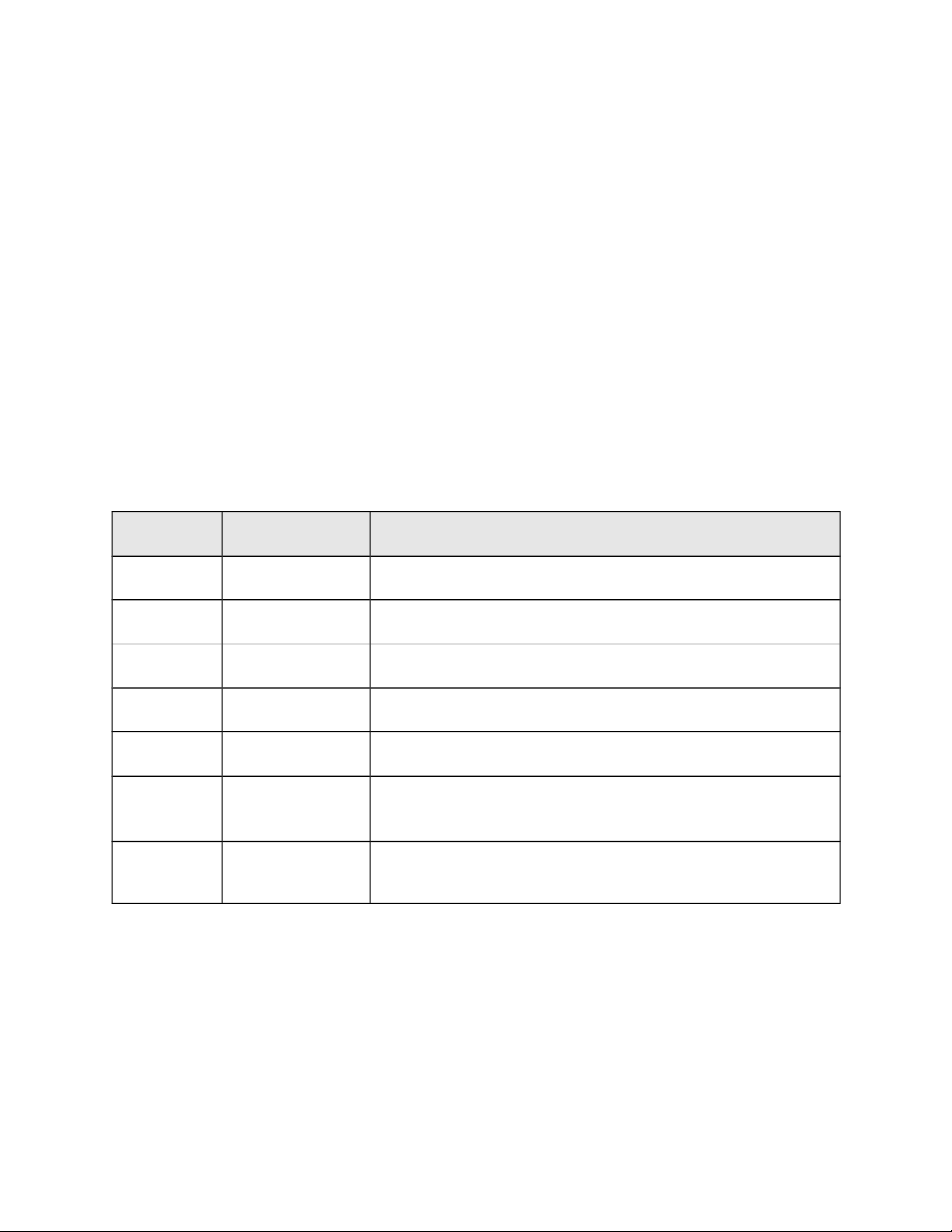
Calculated Expressions in XML Gauges
Values of some elements require “calculated expressions.” Examples of calculated expressions
are the <Visible> element or the <Value> sub-element of the <Rotate> element. These
expressions define what a needle or a dial shows. In their simple form, these expressions are the
names of simulation parameters and the units in which an element wants the parameter to show,
enclosed in parentheses. In the following code fragment, taken from the altitude gauge, the
needle is rotated, based on the value of the “Indicated Altitude” parameter, in feet:
<Rotate>
...
<Value>(A:Indicated Altitude, feet)</value>
</Rotate>
The “A” before the semicolon indicates that this parameter is an aircraft
parameter. “Indicated Altitude,” as stated earlier, is the aircraft parameter
and “feet” is the unit of measure in which the aircraft parameter will
display. The following table describes all kinds of parameters.
Parameter Stands for… Description
A Aircraft
Get the current parameters of the aircraft.
E Environment You can get the current time from this parameter.
P Program related You can get the simulation rate from this parameter.
G Gauge variable A variable that is local to this particular gauge.
L Local This parameter can be any user-defined variable.
K Key code Variables of this kind are key codes that are sent from
gauges to Flight Simulator.
M Mouse variables This parameter reports the state of the mouse for use in
mouse click handlers.
For more information on possible parameters for “A”, “E” and “P” see the Parameters.doc
document in this SDK. A unit name is required after the parameter name. For
the list of recognizable unit names go to Units.doc document in this SDK.
Parameters of the “G” kind have names of “Var1”, “Var2”, … “Var9”, etc. They give you the
values you assign to them. Don’t put unit names after them.
Use your own names for parameters of “L” kind. Use unit names after them.
For more information on parameters of the “K” kind, see the EventIDs.doc document
in this SDK. Do not use unit names after these parameters.
98
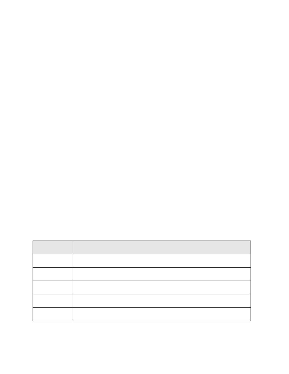
Parameters of the “M” kind are:
• “X” — the X coordinate of the mouse pointer.
• “Y” — the Y coordinate of the mouse pointer.
• “Event” — the string representation of the event which triggered the mouse handler.
Examples of the string event are “LeftSingle”, “RightDouble”, “MiddleDrag”, “Move”, and
“LeftRelease”.
If you want a gauge to show altitude in thousands of feet, divide the value of the “Indicated
Altitude” parameter by 1000. For example:
<value>(A:Indicated Altitude, feet) 1000 / </value>
To execute an arithmetic operation, put both operands first in the markup language
((A:Indicated Altitude, feet) and 1000 in the code above) and then include the symbol
of operation (/). This is how some programmable calculators performed arithmetic operations in
the past.
This convention works the following way: When the parser sees the first operand, it pushes that
operand onto the top of the internal stack. The parser then pushes the second operand onto the
stack. When the parser reaches the operation symbol, both operands are popped from the stack,
the operation is performed, and the result is pushed back onto the stack. Whatever value is on top
of the stack at the end of the execution is the result of the calculated expression.
There are a number of operations that you can use in calculated expressions. The following
sections list the operators you’d use for various operations.
Common Operators
Some operators, like those in the following table, are well known to programmers.
Operator Operation
+ addition
- subtraction
/ division
* multiplication
% taking modulo
Comparison Operators
You can use the following operators for comparison.
99
Operator Operation
== true if equal
!= true if not equal
> true if 1
st
operand bigger
< true if less
>= true if more or equal
Bit Operators
The following bit operations are familiar to “C” programmers:
• &
• |
• ^
• ~
• >>
• <<
Logical Operators
Logical operations are:
• !
• &&
• ||
• /-/ (negates a number)
Numerical Operators
Numerical functions available are:
abs cos lg min sin
acos ctg ln neg sqr
100
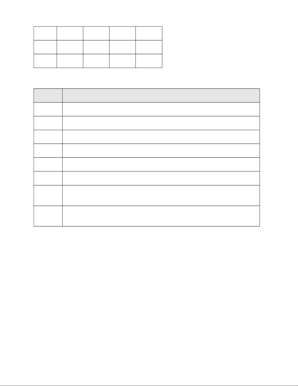
asin eps log pi sqrt
atg2 exp max pow tg
atg
The following numerical functions are not obvious and require some explanation.
Operator Operation
div Divides integers; its result is always an integer.
flr Calculates nearest integer number which is less than the source number.
ceil Calculates nearest integer number which is bigger than the source.
near Calculates the nearest integer number.
rddg Converts radians to degrees.
dgrd Converts degrees to radians.
rnor
Normalizes an angle expressed in radians. The result of this operation is between
0 and 2π.
rdeg Normalizes an angle expressed in degrees. The result of this operation is between
0 and 360.
101
String Operators
Operations for working with strings are as follows.
Operator Operation
lc Converts a string to lowercase.
uc Converts a string to uppercase.
cap Capitalizes a string.
chr Converts a number to a symbol.
ord Converts a symbol to an integer.
scat Concatenates strings.
schr Finds a symbol in a string.
scmp Compares strings.
scmi Compares strings, ignoring case.
sstr Finds a substring.
ssub Extracts a substring.
symb Extracts a single character.
To push a string into the stack, put the string between apostrophes (for example: ‘LeftSingle’).
The “?” and “case” operators are selective operations. The third operand of the “?” operation
defines which operand, first or second, is the result of the operation.
Stack Operators
The following set of operations enables you to work with the stack.
Operator Operation
c Clears the stack.
d Duplicates the value that is on the top of the stack.
p Pops and discards the top value on the stack.
102

r Reverses the top and second values on the stack.
s0, s1, … s49 Stores the top values in internal registers.
l0, l1, … l49 Loads values from the registers on the top of stack.
sp0, sp1, … sp49
Stores the top value and pops it from the stack.
103

Order of Execution for Operators
The order of execution of operations doesn’t have to be sequential.
There is an “if” facility and there is a “goto” facility:
• The “if{” facility pops the top value from the stack and, if it’s a “true”
value, executes operations between “if{” and “}”. Note: there is no space
between “if” and “{”. The “els{” operation follows, closing “}” of the
“if{” operation. The “els{” operation lets operations between “els{“ and
“}” execute only when the operand of the “if{“ operation evaluates to
“false”.
• The “goto” facilities consist of the “g0”, “g1”, “g2”, “g<any number>” operation, which
jumps execution flow to the corresponding label. The “:0”, “:1”, “:2”, “:<any number>”
operation defines those labels.
104

Appendix A: Tips on Creating Art for Panels
and Gauges
This Appendix provides some general guidelines you might find useful as you create artwork for
your panels and gauges. It assumes you have some general familiarity with graphic design and
associated tools.
Background
In Flight Simulator 2004 2-D art is used to represent the aircraft panels in non-virtual cockpit
mode. The panel is broken down into many files stacked on top of one another. The cockpit
background is a separate bitmap that has the individual gauges placed over it. Currently, the
shadows of the gauges are placed on the panel background. The gauges themselves are not
realistically three-dimensional and do not represent accurate depth relationships. This limitation
is deliberate because it gives you the ability to position the gauges on the panel wherever you
prefer.
The most important feature of a Panel system is its readability. The panel should not only be
convincing, but it must look acceptable at any resolution.
Learning About the Aircraft
Before beginning work on a panel, you should have a good understanding of what you will be
working on. Familiarize yourself with the aircraft and its capabilities. Gather as much
information as possible on the panel.
Once you have gone through the reference material for the plane, compare the panel with those
of other aircraft. You will always have to create the background of the specific cockpit, but
sometimes you can use gauges from a different panel. These gauges may resemble the gauges for
your aircraft even though they are not an exact replica. Originality is always important, but
sometimes choosing a generic gauge background or a set of type can save you an hour or two.
105

Creating a Layout for the Panel
Researching the Instruments
Now start thinking about the look and feel of the cockpit. Find out which instruments you should
include in the layout. Create a priority list of instruments and go through it with anyone with
knowledge about what’s important to include in the cockpit. Talk with pilots and get an idea of
what people want to see. Unless you know a fair amount about aviation, you may overlook
something that is critical for efficient flight/navigation.
Creating the Layout
Once you have a list of what needs to be included on the panel, create a layout of what the panel
is going to look like. The layout can be the most difficult part of creating a panel. However, the
goal of the layout is very simple: you want the panel to retain its original look and feel while
allowing the most space for instruments. Even a few pixels can make a difference when making
room for instruments. Make sure that all the instruments stay in proportion to each other and
with the panel background. Remember, this is only a layout and it can look a little rough. Some
artists like to create layouts by drawing them,. while others find that cutting and pasting the raw
photographs in a program like Photoshop is easier.
Considering the Panel Height
One concern you may have when you create a layout will be the height of the panel. A panel that
is too high will decrease visibility for the user. This was a major concern in the first version of
Microsoft Combat Flight Simulator, which depended on visibility for game play. It was therefore
decided that the panel height in Combat Flight Simulator would be 50 percent of the screen size.
This was a fair compromise between game play and usability of the panel. Flight Simulator 2004
is not so dependent on outside viewing, so creating a taller panel is acceptable if it is a better
representation of the real-world layout.
Considering the Slope of the Sides
The slope of the panel’s sides is another thing to consider. If the sides are pitched too steep,
performance will be lost due to the larger 3-D window. Raising the 3-D window a few pixels can
increase performance. If the sides are not pitched very much, the panel will appear flat, without
dimension.
106

Beginning Production
Creating the Base Background
You may want to begin with the panel background. This piece of art can take a long time to
create, especially when it is your first or second panel. Make sure that you spend the time needed
in making the background seamless. Use layers to your advantage in creating depth.
If the photograph that you work with is too difficult to clean up, use flat colors to make the
background’s base. Then add a gradation, usually lighter on top to darker on the bottom, and
some sort of noise or texture to give more depth. You can often achieve similar results by
cleaning a background with filters and gradation.
Adding Depth and Detail
Once the base has been established, add subtle depth and detail. Scratches, nicks and paint chips
can add a lot of character and realism to a panel. Over time, you may want to create a library of
such details. Apply them through the aid of opacity and layer options. Each case is different.
Experiment with what looks best.
Merging the Side Panels
After you have established the base background, begin working on how the side panels will
merge into the background. Often, you can place a seam or crack over the two layers, which
helps blend the two together. You can take these cracks or seams from any cockpit photograph;
otherwise, you may have better luck drawing a seam, although you may find that drawn cracks
often appear a bit too perfect.
Creating the Panel Edge and Shadow
Over the base background and sides will be the edge of the panel and its shadow.
Make the edge of the panel as thin as possible without sacrificing the cockpit’s character. A thin
edge can look wimpy, while a thick edge, as real as it may be, will be a waste of space. You may
want to keep these two elements as separate layers for flexibility in making changes later.
Shadows are usually between 50 percent and 60 percent opacity, which gives the panel depth but
does not create shadows that are too overpowering. The lighting in Flight Simulator typically
represents an overhead softer light source (e.g., a hazy day at noon). If you choose a direction of
light, note that it may not match the outside of the plane or landscape. Use your artistic judgment
to make these decisions.
Compressing the File
When the panel background is close to complete, make a copy and compress it into an 8-bit file.
If banding occurs in the shadowed areas, you may have to lighten or darken the shadow to make
it look smooth. This, of course, will vary depending on which program you use to compress your
files into 8-bit.
107

Building the Gauges
Separating the Gauge Elements
When creating instrument gauges, try keeping as many elements separate as possible. This will
enable you to easily add library elements to your instrument without having to do a lot of work.
Working at a Larger Size
You’ll probably find it useful to work in a larger size than that which the gauge will be resized
to. If appropriate, start with the original scanned photograph and work from a copy. This will be
helpful as you clean up the instrument and still need a reference.
Cleaning the Rings and Backgrounds
The first thing to do is clean up the ring and background of the instrument.
Make sure the lighting remains even across the ring (with no hot spots from the lighting). Hot
spots give a false impression of where the sun is coming from.
Keep as much detail as possible, which gives the gauge character.
Create a copy of the inside of the gauge (the gauge face) where the glass covers it, and make this
a separate layer.
Remove the inside of the gauge from the original layer to clean up the edge of the ring.
Now you can lighten or darken the gauge background without changing the tone of the inside.
Adding Depth and Details
Working on the inside the gauge face, remove the needle and make it into a separate layer.
Next, clean up the existing art, or lay down a color, then add a texture or noise on top to add
depth. You may want to apply a different “clouds” filter to the gauge face to make it look a little
more natural.
With the ring layer over the face layer, create a little drop shadow from the ring to add depth to
the gauge. Make sure this is on a separate layer for flexibility. You may want to add a light-black
Gausian-blurred ring over the gauge face to show that it has a round feel to it. These are subtle
features that add reality to the artwork.
Now create another layer. With the original raw photograph as a guide, draw the tick marks of
the instrument. Try to make these tick marks bright and readable so they stand out when you
resize the gauge later.
Finally, return to the needle layer and strip the needle from the background. Make sure that the
tonality of the needle does not blend into the new gauge face.
108

Compiling the Gauge
To compile your gauge, create another layer and merge all of the gauge elements, except for the
needle, into that layer, while retaining the existing elements. Once you’ve done this, you have a
compiled gauge and all of its elements and its separate needle are ready for resizing.
Resizing the Gauge
Note! Make sure that you save your work before you begin resizing. (If you need to make any
adjustments to the gauge, you can change the element and then re-merge that element onto the
compiled layer without having to repeat a lot of work.)
Make a copy of the compiled instrument layer and place this into a separate file.
Copy the needle into the new file to resize both at once.
Resize the file to 1024x768 resolution.
Now, add the type to the gauge (referring to the larger original file for reference). Explore the
fonts on your computer and choose one that matches the typeface of the gauge.
Create another layer and merge the compiled gauge with the type layer. Sharpen this layer and
the needle layer. Save this file for any future adjustments.
Next, make the two layers into separate files. When making these separate files, clean up the
edges of the file by giving it an aliased edge. It will save time later when you compress the 24-bit
file to 8-bit.
Make the backgrounds of the files true black (0,0,0 RGB value). True black appears transparent
in the simulation.
Place these files into a separate folder, which represents the 1024 art ready for 8-bit conversion.
Palletizing the Artwork
You can use a number of programs to palletize your artwork. Try several and choose the one that
works best for you. Note that different pieces of the artwork do not need to use the same palette;
each piece can use its own palette.
Once you’ve converted the files to 8-bit, save them as a separate file and place them in a folder
labeled “Completed Art” (or something that lets you know the art is ready for final use).
Check to see if pixels with the values of 0,0,0 and 1,1,1 are where they should be.
109

Creating a Final Composition
Once all the artwork is complete, assemble the artwork into a final composition for the entire
panel.
Double-check to see if there are any mistakes or if something doesn’t look right. It is inevitable
that you will have to change something. Make the appropriate adjustments and then add the new
artwork to the final composition.
110
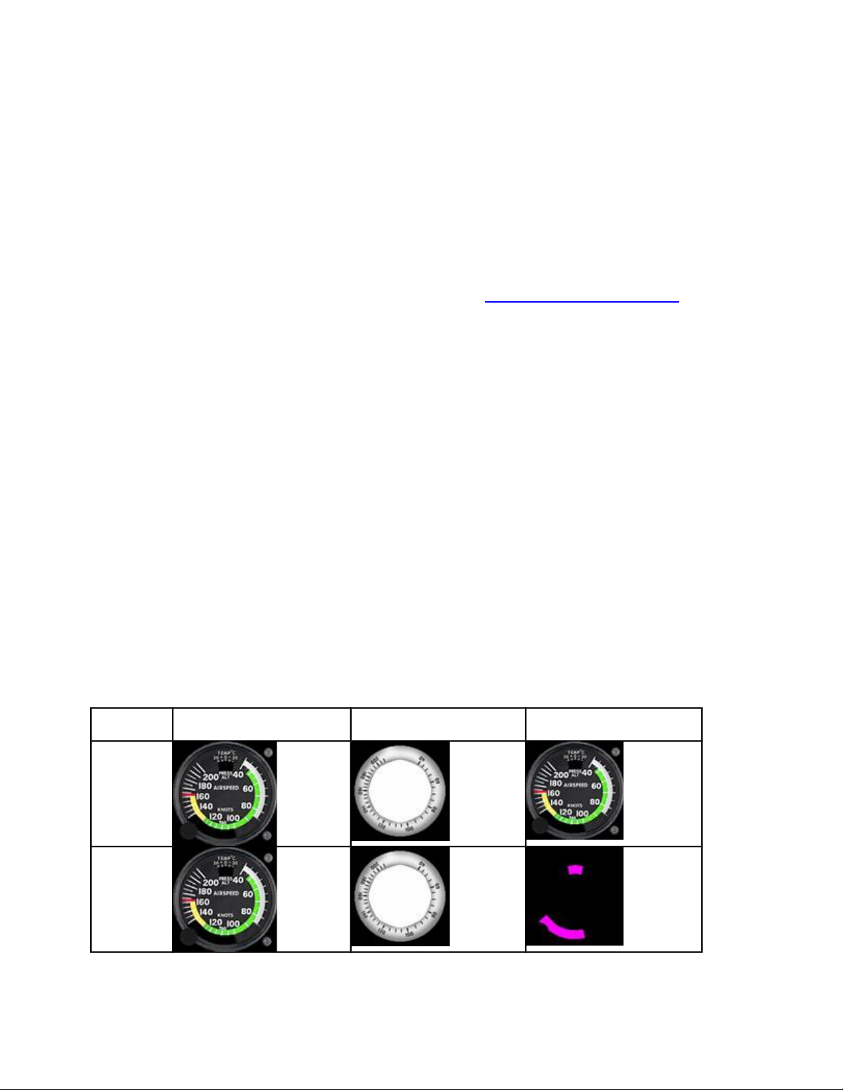
Appendix B – Using Masks in Images
A mask image allows a gauge designer to create a “hole” in a layer (think gauge layer, not a
Photoshop .psd layer) so that a piece of the gauge can be seen “through” another piece.
A mask image is determined by one of two things:
• In an XML-specified gauge, the <MaskImage> element is used as a sub-element of a gauge
<Element>. In other words, the <MaskImage> and <Image> elements are siblings. For an
example of an XML-based magnetic compass, see the Step-by-Step XML Example: later in
this appendix.
• In a C-specified gauge, an image is specified for a Sprite or MovingImage element. The
mask image for the element is based on the resource ID specified for the sprite/moving
image. (The mask image’s resource ID is one greater than the image.)
How Do I Use a Mask Image?
For example, let’s look at the airspeed indicator for the Cessna 172, which has a TAS
component. Through the “window” in the gauge background, you can see the “airspeed card”
(the rotating bit the user can adjust based on altitude and temp).
There are two ways to generate such a hole:
• Method 1: Specify a transparent area in a static image that also displays other things (for
example, tick marks and other graphics associated with a gauge).
• Method 2: Create a mask image used solely to specify which area of its associated element to
display. This is similar to specifying a transparent area in a static image, except that no
visible graphics need to be associated with this type of mask.
Here’s a graphical depiction of the above (black is transparent in all images):
Background image
(bottom layer)
Element Mask Image
Method 1
Method 2
Note that the magenta used in the Mask Image is actually of RGB value 1,1,1 (very close to
black). When you see these images in drawing programs, they appear completely black.
111
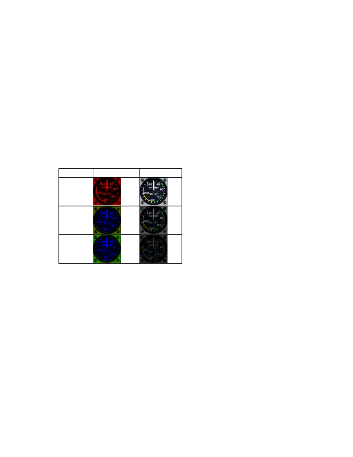
The apparent advantage of using method 2 is size savings. A monochrome bitmap can be used to
generate mask image #2.
In the example above, the TAS card (the rotating bit) is actually ABOVE the background in the
Z-order, even though it appears to be behind the background.
Specifying Luminousity
The panel and gauge developer can specify three colors in the panel.cfg for “Day”, “Night”, and
“Luminous.” Day and Night effectively determine the maximum and minimum brightness of the
panel. Luminous specifies the color that can be applied to the luminous sections of the gauges.
Here is a somewhat extreme example to demonstrate what these colors mean. In this example,
the colors for day, night, and luminous are defined as red, green, and blue. Note the subtle
difference between Dusk and Night – the environmental lighting conditions determine what
percentage of the day color to use.
Lights On Lights Off
Midday
Dusk
Night
In the example above (which happens to be the Extra’s airspeed gauge), the luminous section of
the gauge (in the middle) has the luminous color applied, which is blue (0, 0, 255). When lights
are off, no .cfg-specified color is applied to the panel and its gauges – the brightness of the
images are affected, however, by the environmental lighting (such as the height of the sun in the
sky, moonlight, etc.).
Imagetool and Luminousity
The Flight Simulator 2004 gmax SDK includes Imagetool, which recognizes certain .bmp’s as
having a monochrome alpha channel. The “alpha channel” has nothing to do with alpha-
blending. Instead, it’s used to determine what section of the image is to be illuminated at night
when panel lights are on.
Typically lighting effects get applied to an entire panel, but the LUMINOUS COLOR is applied
to the section of the gauge(s) specified by this alpha channel. The area of the image with the
alpha channel looks different when viewed with Photoshop or Imagetool:
• In Photoshop, the area of the alpha channel that appears WHITE will have the luminous color
applied.
112
• In Imagetool, the area of the alpha channel that appears BLACK will have the luminous color
applied.
When Imagetool displays the image (not the alpha channel) of the bitmap, it displays the area
that will have the luminous color applied as completely BLACK (which some may find
confusing as black typically indicates transparency).
Note: You can create images with an alpha channel using either Adobe® Photoshop® or
Corel® Painter™. Corel Painter supports greyscale alpha channels and will save as a .psd (with
an alpha channel).
How Colors Affect the Display of Panels.
The color of a pixel is adjusted as described below.
If lights are off: use the environmental lighting value (an 8-bit value) to scale the r,g,b
components of that pixel. Thus only brightness, not tinting, is affected.
If lights are on:
• For the luminous section of the panel, the luminous color is only used if the
environmental lighting (sunlight, which depends on the time of day) is less than a certain
value, which happens around dusk. Thus, during the day the luminous color is not
applied to the panel at all.
At night, each pixel is scaled by the luminous color specified in the panel.cfg. That is,
each RGB component of each pixel is scaled by the luminous color. For example, the red
component of a pixel would be changed to the current red value, multiplied by the red
value of the luminous color, and divided by 255 (since there are 8 bits per color channel)
as illustrated in the following formula:
R_New = R_Old*(R_Luminous/255).
• For the non-luminous sections of gauges, the luminous color isn’t used – instead a
combination of the day and night values is used.
o If it is completely light out, the day color is used.
o If it is completely dark out, the night color is used to scale.
As the time transitions from day to night, the panel’s tint is gradually scaled between the
day and night colors. Thus, tint = night + (day – night)*sunlight/255. (Where sunlight is
in the range between 0 and 255). The formula below illustrates this:
R_New = R_Old*(tint/255)
This tint value is then applied the same way that the luminous color is applied to
luminous sections of the panel.
113

Step-by-Step XML Example:
<Gauge Name="magnetic_compass" Version="1.0">
<Image Name="magnetic_compass_background.bmp"/>
<!-- ======================= Compass Strip ======================= -->
<Element>
<Position X="21" Y="26"/>
<MaskImage Name="magnetic_compass_window.bmp">
<Axis X="32.5" Y="0"/>
</MaskImage>
<Image Name="magnetic_compass_strip.bmp">
<Nonlinearity>
<Item Value="0" X="294" Y="0"/>
<Item Value="360" X="50" Y="0"/>
</Nonlinearity>
</Image>
<Shift>
<Value>(A:Wiskey compass indication degrees,degrees) dnor</Value>
</Shift>
</Element>
<!-- ======================= Tick Marks ========================= -->
<Element>
<Position X="51" Y="27"/>
<Image Name="magnetic_compass_line.bmp"/>
</Element>
<!-- ======================= Shadow ============================= -->
<Element>
<Position X="0" Y="0"/>
<Image Name="magnetic_compass_shadow_alpha.bmp" Alpha="Yes"/>
</Element>
<!-- ======================= Highlight ========================== -->
<Element>
<Position X="0" Y="0"/>
<Image Name="magnetic_compass_highlight_alpha.bmp" Alpha="Yes"/>
</Element>
<Mouse>
<Tooltip ID="TOOLTIPTEXT_WHISKEY_COMPASS"/>
</Mouse>
</Gauge>
114
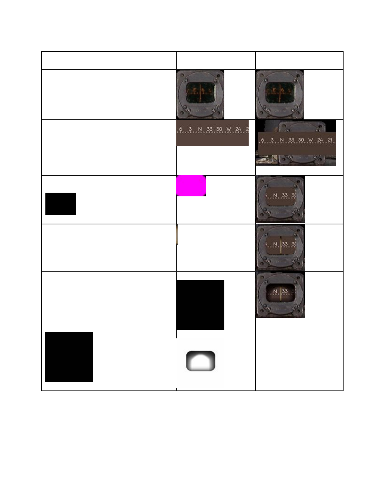
Examining the gauge, adding one image at a time:
Description Image Image added to lower
layers
Background: Note that some parts of the
background image will be covered by
other gauge elements
Compass strip: this element has a shift
applied to it, which makes it move.
(Image truncated)
(Image truncated)
Mask image for compass strip: This
image appears like this in Imagetool:
(Mask pixels in magenta)
Center line: a static image, this could
have been part of the background and the
mask, but making this a separate element
makes it easy to adjust one element’s
position when needed, instead of two.
Shadow: The RGB image is what is
alpha-blended with the underlying layers.
The alpha channel determines how much
of the RGB image is blended (i.e., how
opaque it is). This image appears like this
in Imagetool by default:
RGB image:
Alpha channel:
115
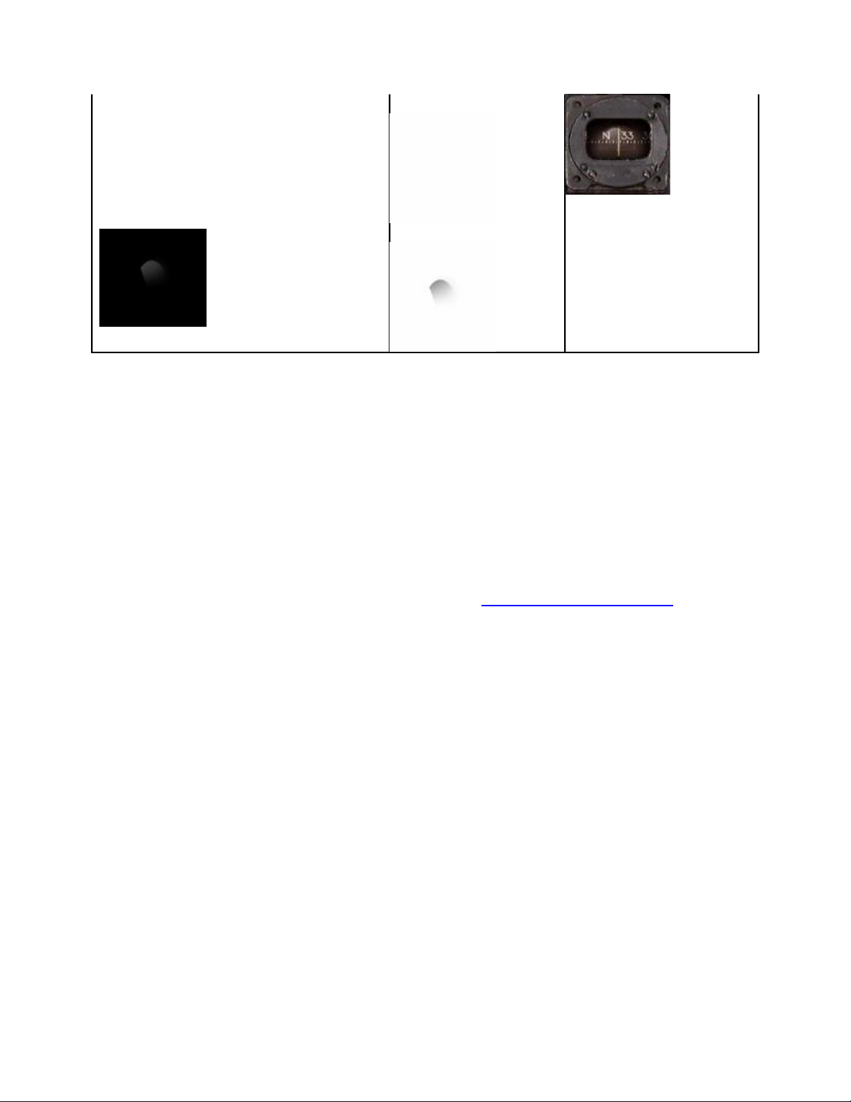
Highlight
Note that in Imagetool, the combination
of the RGB and alpha channels will be
displayed by default – which appears like
this:
RGB image (pure white)
Alpha Channel:
Notice how the addition of the shadow and highlight alpha images increases the level of realism
in the gauge.
Questions about Using Masks in Images
Q: In an XML gauge, what does an image that has “Alpha=Yes” do?
A: There can be a separate gauge element — a static image that has “Alpha=Yes” set.
These are usually one of (if not the) topmost elements of a gauge in the z-order. They are
usually used to set highlights or shadows by using a white or black RGB image combined
with an alpha channel containing a gradient. See the Step-by-Step XML Example for more
information.
###
Q: Is it possible to use Imagetool to convert a 32-bit .bmp with alpha (from Photoshop) to
an 8-bit .bmp with alpha for use with FS?
A: Yes, Adobe Photoshop supports this file format now. However, Flight Simulator will not
recognize this file format, so Imagetool must be used to convert the image to 8-bit-with-
alpha. Run “imagetool –gauge <filename>” from the command line.
###
Q: What the deal with .psd’s?
A: By using Imagetool, you can convert .psd’s into .bmp’s. The visible layers in the .psd get
used to generate the bitmap. An alpha value < 108 results in a transparent pixel; an alpha
value ranging from 109-147 results in a mask pixel, and other values result in an opaque
pixel. This method is slightly superior to the method of specifying the mask pixels and
transparent pixels in the layer itself due to the fact that black and almost-black look almost
exactly the same – an artist could accidentally specify a mask pixel where a transparent pixel
was desired.
116

Q: Can 3
rd
-party developers create gauges without .cab’ing their .xml and .bmp’s like we
do?
A: Yes, the .xml files and .bmp’s can simply be stored in a directory with the name of the
aircraft in the panel directory.
###
Q: How is it possible that we have an 8-bit format that can store an alpha channel? I
thought bitmaps had to be 32-bit to do such a thing.
A: An 8-bit format can indeed store an alpha channel. In Flight Simulator’s 8-bit indexed
format, the palette contains 32-bit colors, enough for an alpha image (these palettes usually
only contain 24-bit colors).
Note that Photoshop does not support such a file format. (You can neither save to this format
nor view the alpha channel for such a file – see the 747’s analog_attitude_alpha.bmp for an
example of a 256-color .bmp that has many colors AND an alpha channel.)
Imagetool will only create an “alpha image” from a 32-bit image. An alpha value < 108
results in a transparent pixel, 109-147 results in a mask pixel, and the rest result in an opaque
pixel.
However, it should be noted that if the “-gaugealpha” flag is specified, those numbers do not
apply – the alpha channel is used to specify alpha-blending characteristics, not a mask for
another image.
###
Q: If you see grey in the alpha channel for an image in the Imagetool, what does that really
represent?
A: It depends. It could represent a section of mask pixels. Or it could represent the alpha-
blend level to apply to another image, depending on the context in which the image is used.
117

Appendix C – Using Imagetool with Gauges
Imagetool includes many methods for manipulating images used in Flight Simulator. However,
most of those features are used for other areas of the simulation besides gauges (terrain, etc.).
Gauge developers can, however, create images of the correct format for use in Flight Sim gauges
by using ImageTool. The major uses of Imagetool for gauge developers are as follows:
• Convert .psd’s to Flight Simulator’s proprietary .bmp-with-alpha format
• Convert a .psd to a .bmp with mask pixels, based on the image’s alpha channel.
• View images created with ImageTool.
Imagetool is also an easy way to:
• Determine the format of an image
Converting .psd’s to .bmp-with-alpha format, maintaining alpha
channel
There are two ways to do this: by running the tool from the graphical user interface (GUI) or the
command-line.
GUI
1. Open the file by using the File->Open menu command.
2. In the Image->Format menu, choose the format you wish to convert to (8-Bit).
3. Save the file by using the File->Save menu command.
Command-line
1. Open a command window by running “cmd.exe” from the Start->Run dialog.
2. From the command line, run “imagetool –gaugealpha [filename]” where [filename] is the
name of the file you wish to convert. (Note: This flag is not documented in the Usage
guidelines that appear when “Imagetool -?” is run.) By default the .bmp file generated
will have the same name as the .psd from which it was created. The image generated will
be 8-bit (palletized).
After converting the image to .bmp-with-alpha format by using one of the two methods above,
you can view the alpha channel in imagetool.
Converting .psd’s to .bmp-with-alpha format, creating a “gauge
image”
When a “gauge image” is created, the alpha channel’s pixels are altered as follows:
• If a grey pixel has a value greater than or equal to 148, it is converted to white, which
indicates an opaque pixel.
• If it is between 108 and 147, it is converted to grey, which indicates a mask pixel.
• Pixels with values less than 108 are converted to black, which indicates a transparent
pixel. Additionally, the RGB channel is modified so that transparent pixels are black and
mask pixels are of RGB value 1,1,1.
118
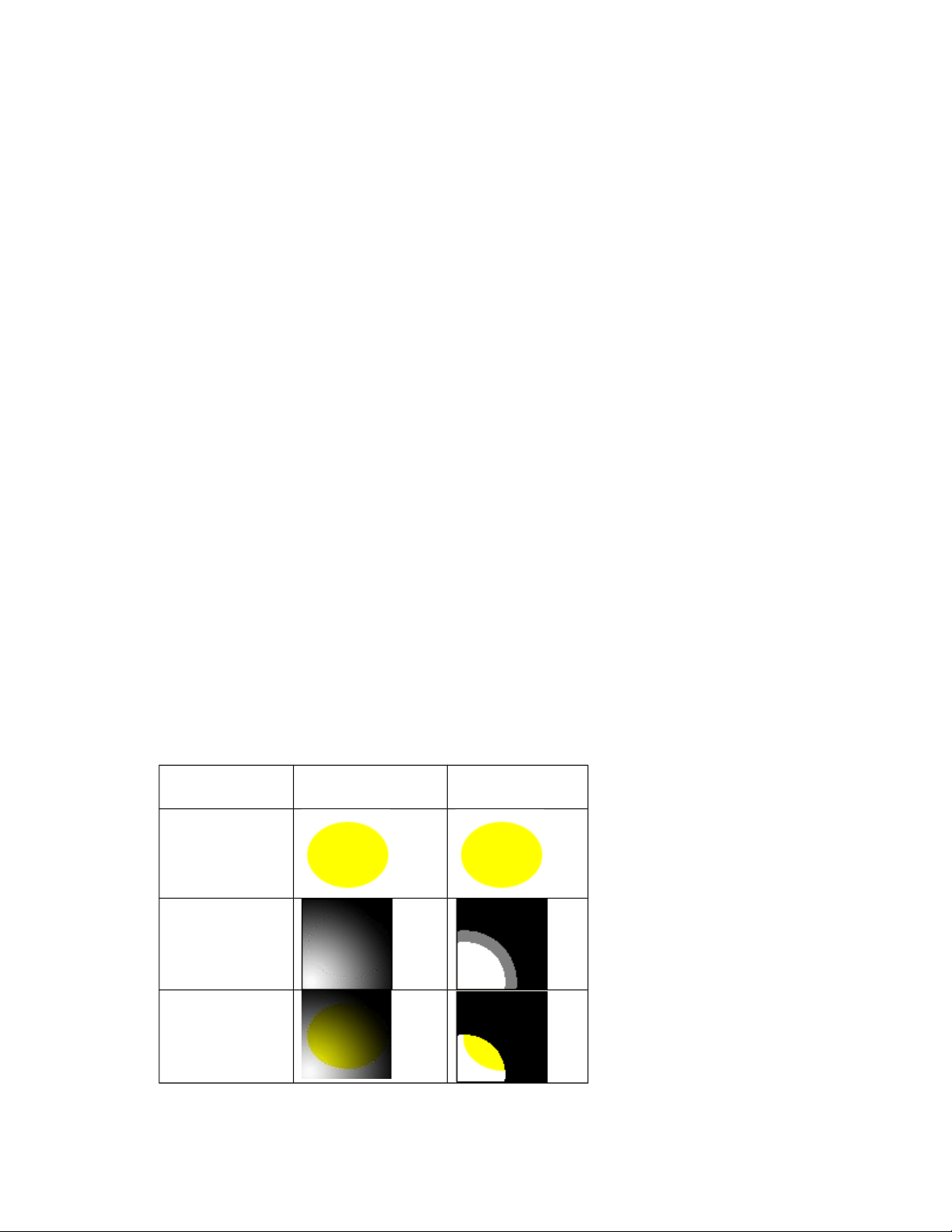
There are two ways to create a “gauge” image: by running the tool from the graphical user
interface (GUI) or from the command-line.
GUI
1. Open the file by using the File->Open menu command.
2. Select the Image->Make Gauge menu item.
3. Save the file by using the File->Save menu command.
Command-line
1. Open a command window by running “cmd.exe” from the Start->Run dialog.
2. From the command line, run “imagetool –gauge [filename]” where [filename] is the
name of the file you wish to convert. By default the .bmp file that is generated will have
the same name as the .psd from which it was created. The image generated will be 8-bit
(palletized).
After converting the image to .bmp-with-alpha format by using one of the two methods above,
you can view newly created image and its alpha channel in imagetool.
Viewing images created with ImageTool
Because Flight Simulator uses a unique file format (.bmp-with-alpha), ImageTool is the best way
to view these images. The default view in ImageTool displays a combination of the alpha
channel and the RGB channels. The way this alpha channel is applied depends on the way the
image was created:
• If the alpha channel was maintained during the file conversion, the alpha channel is
applied in the following manner: the brighter the pixel in the alpha channel, the brighter
the RGB pixel is drawn.
• On the other hand, if a “gauge image” is viewed, the alpha channel is not applied in the
default view – only the RGB channel is visible.
“Alpha channel”
image
“Gauge” image
RGB
Alpha channel
(as viewed in
ImageTool)
Default view in
ImageTool
To view the alpha channel separately, choose the menu option View -> Alpha Channel.
119

Determining the format of an image
To determine the format of an image, click on Image->Format in Image Tool.
120