Back to FS2004 SDK Overview

Microsoft Flight Simulator 2004 gmax Aircraft Creation doc
Microsoft
Flight Simulator 2004:
A Century of Flight
Software Development Kit
© 2003 Microsoft Corporation. All rights reserved.
Discreet and gmax are trademarks of Discreet Logic Inc./Autodesk, Inc., in the U.S.A. and/or
other countries.
gmax Aircraft Creation document
November 2003
© 2003 Microsoft Corporation. All rights reserved. Page 1 of 20

Microsoft Flight Simulator 2004 gmax Aircraft Creation doc
Contents
........................................................................................................................................................2
Introduction....................................................................................................................................3
Getting Started................................................................................................................................4
Setting Units of Measurement ..................................................................................................4
3View Drawings.........................................................................................................................4
LODs...........................................................................................................................................5
Heirarchy....................................................................................................................................6
The Exterior Model........................................................................................................................6
Polygon Counts..........................................................................................................................6
Textures .....................................................................................................................................6
Special Material Names.............................................................................................................9
Animating Textures...................................................................................................................9
Tires and Props........................................................................................................................10
Animations................................................................................................................................11
Pilots..........................................................................................................................................12
The Interior Model.......................................................................................................................12
Polygon Counts........................................................................................................................12
Textures and Virtual Texture Sheets.....................................................................................12
Animating Textures.................................................................................................................17
Animations................................................................................................................................19
Special Material Names...........................................................................................................19
Eyepoints...................................................................................................................................19
Exporting the Model.....................................................................................................................20
Exporting the Model................................................................................................................20
Converting Textures................................................................................................................20
© 2003 Microsoft Corporation. All rights reserved. Page 2 of 20

Microsoft Flight Simulator 2004 gmax Aircraft Creation doc
Introduction
Microsoft
®
Flight Simulator 2004 A Century of Flight Edition supports models created in gmax,
a 3-D modeling tool from discreet. By using gmax, you can create a model of an aircraft, apply
textures and animations to that model, and then export the model to the MakeMDL program,
which creates the format for use in the product.
The Aircraft Creation document is NOT a tutorial on how to use gmax to create an aircraft.
Rather, it provides a set of best practices to follow when using gmax to build aircraft for use in
Flight Simulator. This document focuses on the following four areas:
• Getting Started: a brief summary of what needs to be in place before modeling.
• The Exterior Model: everything you need to create an exterior model.
• The Interior Model: everything you need to create an interior model.
• Exporting the Model: you export the model to the MakeMDL program, and then place
the model in the appropriate aircraft container within Flight Simulator.
Files Required:
• MSXML4 available on www.microsoft.com
• Curtiss Jenny.gmax in \gamepack\FS2004\scenes
• _Panel_Jenny_1.tga in \gamepack\FS2004\texture
• _Panel_Jenny_2.tga in \gamepack\FS2004\texture
• Curtiss_Jenny_C_1.tga in \gamepack\FS2004\texture
• Curtiss_Jenny_C_2.tga in \gamepack\FS2004\texture
• Curtiss_Jenny_T.tga in \gamepack\FS2004\texture
• Decal_nnumber.bmp in \gamepack\FS2004\texture
• Decals.tga in \gamepack\FS2004\texture
• Prop_Jenny.tga in \gamepack\FS2004\texture
• VCRainMoving0000.tga in \gamepack\FS2004\texture
• VCRainStopped0000.tga in \gamepack\FS2004\texture
• Aircraft.cfg in \gamepack\FS2004\extras
• Imagetool in \gamepack\FS2004\tools
© 2003 Microsoft Corporation. All rights reserved. Page 3 of 20
Microsoft Flight Simulator 2004 gmax Aircraft Creation doc
Getting Started
In this section, we will cover general information that pertains to gmax and modeling procedures.
Topic Explanation
Setting Units of
Measurement
In Flight Simulator
2004, all dimensions
are measured in
meters, so you must
set the units that gmax
uses to meters.
On the Customize menu, click Units Setup.
In the Units Setup dialog box, click Metric, select Meters from the
Metric box, and then click OK.
On the Customize menu, click Preferences. On the General tab
under System Unit Scale, verify that it reads 1 Unit = 1.0 Meters,
and then click OK.
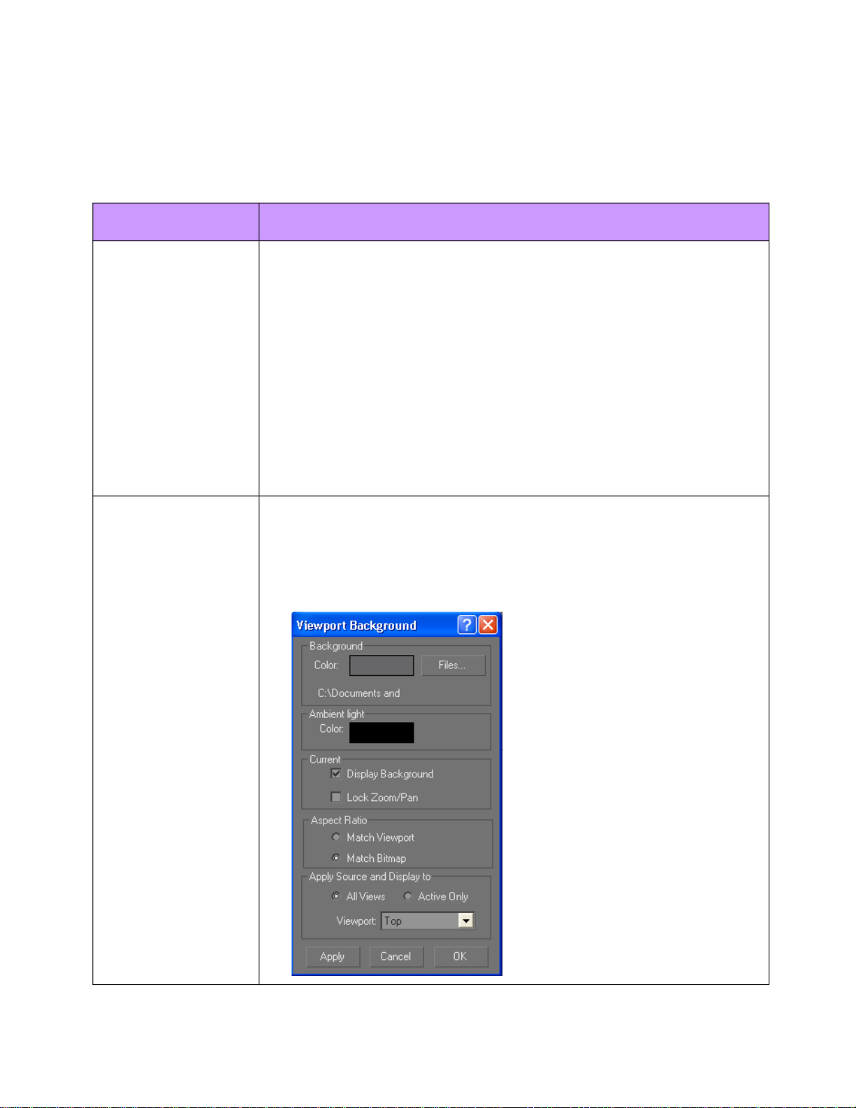
3View Drawings
It is good practice to work through 3View drawings. These should be
separated into front top and side images and loaded into the
corresponding view ports through Views>Viewport
Background>Files… Button
© 2003 Microsoft Corporation. All rights reserved. Page 4 of 20
Microsoft Flight Simulator 2004 gmax Aircraft Creation doc
Topic Explanation
Select Match Bitmap and turn off Lock Zoom/Pan
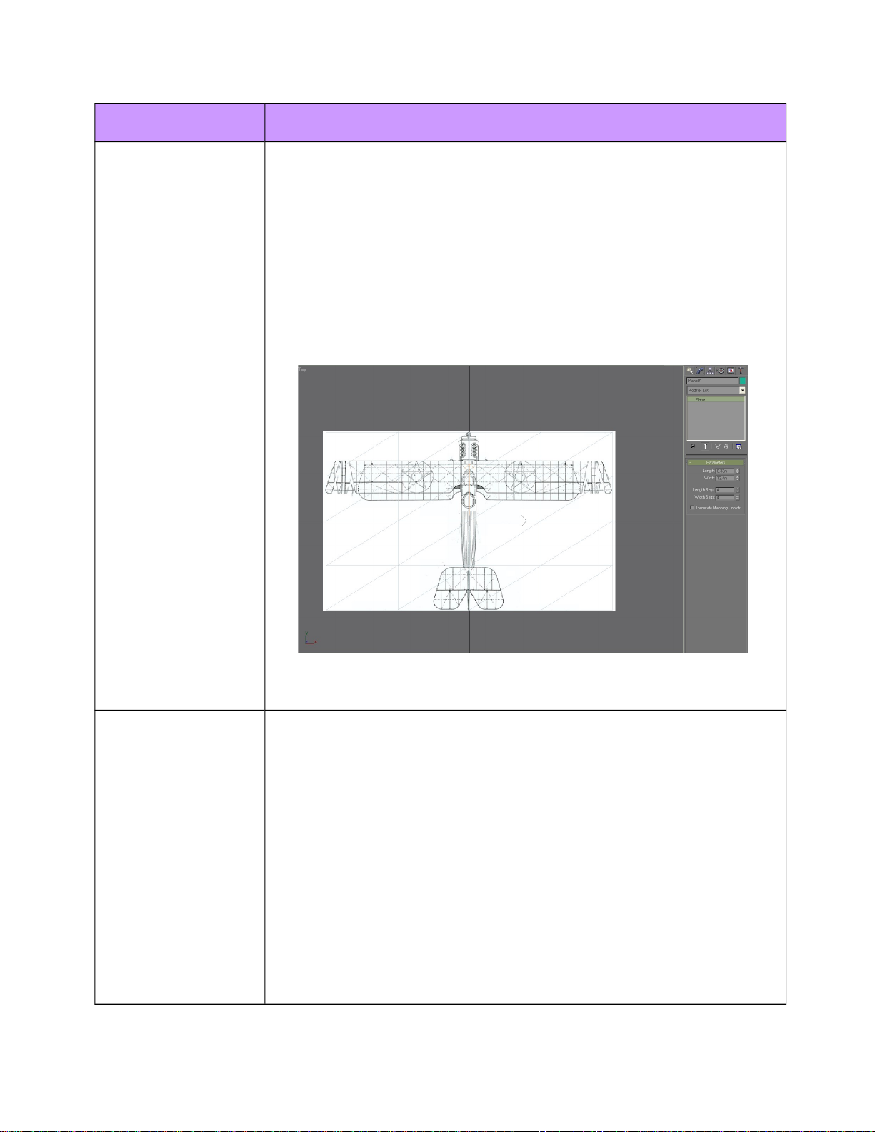
Create a geometrical plane with the dimensions of the aircraft
corresponding to the view chosen.
Zoom in the plane to match the 3 view drawing. Once the size of the
plane and drawing match, check the Lock Zoom/Pan box. This
locks the drawing with the aspect of the plane and allows you to
zoom in and out of both. Do this for all of the three views.
Now you have a template to work from for creating the exterior of
the aircraft and the drawings should have the same aspect ratio.
LODs
For Flight Simulator 2004, we expanded the LOD value range from
000-200 to 000-400. This allows the LODs to switch earlier than
before. This was particularly useful with higher polygonal models.
Our models include 6 LODs in our new exterior aircraft (LOD 400,
150, 75, 35, 15, 5). For this document, we only included the LOD
400 and the LOD 5 models. Our virtual cockpit models do not use an
LOD scheme.
When creating LODs of the aircraft, make sure that every name is
unique. Makemodel does not recognize duplicate parts and can
respond by not exporting one of the duplicate objects.
The per part LOD system will not be supported due to performance
issues. Please see the Makemdl SDK for more information.
© 2003 Microsoft Corporation. All rights reserved. Page 5 of 20
Microsoft Flight Simulator 2004 gmax Aircraft Creation doc
Heirarchy
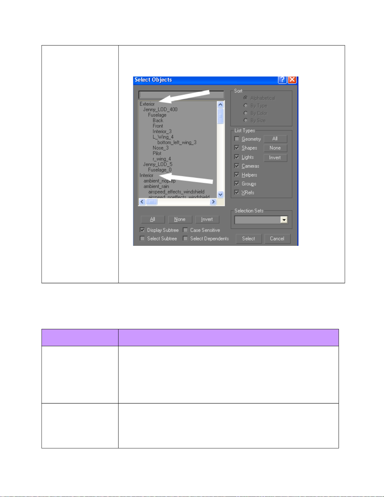
In order to combine the exterior model with the virtual cockpit
model, two top nodes need to be in place. The exterior top node is
named Exterior and the virtual cockpit top node is named Interior.
These nodes need to have an XYZ center of 0,0,0 and be free of any
transform or scaling.
The Exterior Model
In this section, we will cover features of the exterior model.
Topic Explanation
Polygon Counts
The LOD 400 model of the Curtiss Jenny has a triangle count of
nearly 15000 including the pilot. This was an increase of almost
100% from the previous models. We decided to model with more
fidelity because most of the newly featured aircraft are not
included in the AI traffic. Nearly all of the aircraft on the AI plane
list are around 6000 triangles at the top LOD.
Textures
No matter what the texture extension is in the .x file, the
output file (.mdl or .bgl) references a texture with a .bmp
extension. If you model with .tga files, the output file
references a .bmp file.
© 2003 Microsoft Corporation. All rights reserved. Page 6 of 20

Microsoft Flight Simulator 2004 gmax Aircraft Creation doc
We still use the same system for differentiating between non-
damaged and damaged textures. Any texture with an _T
suffix is used as the undamaged exterior texture sheet. Any
texture with an _D suffix is used as the damaged exterior
texture sheet.
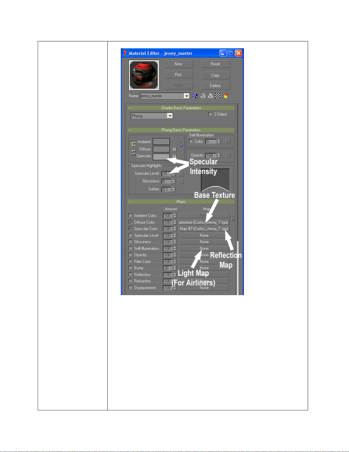
The reflection map texture is the alpha channel in the _T
texture sheet. Load the _T in the specular color channel of the
material to get reflection information. The strength of the
reflection map is determined through the colors of the map in
the alpha channel. Black represents full reflection and white
represents no reflection.
Lightmaps are placed in the self-illumination channel and are
used for night lighting on aircraft such as the airliners.
© 2003 Microsoft Corporation. All rights reserved. Page 7 of 20
Microsoft Flight Simulator 2004 gmax Aircraft Creation doc
All decals used on an aircraft model should Decal_ at the
prefix of its name. If the texture name starts with
“DECAL_” a z-bias is added automatically to all polygons
drawn with this texture.
DECAL_NNUMBER is a generated texture used for generating
the NNumber of the aircraft. The actual texture does not
appear on the mapped geometry. In its place is dev text of the
number generated through the dialog box.
The target amount of texture space that we use on an exterior
model still remains at 1 1024x1024 which includes an 4 bit
alpha channel for the reflection map. In some cases, we gave
additional texture space to larger aircraft or if decals were
© 2003 Microsoft Corporation. All rights reserved. Page 8 of 20
Microsoft Flight Simulator 2004 gmax Aircraft Creation doc
used as in this case.
Special Material
Names
LINE_ = Lines are drawn instead of triangles.
ZBIAS_ = A default z-bias is added to the polygons.
ZBIAS_## = A z-bias of ## is added to the polygons.
DS_ = Polygons are drawn double sided.
BRIGHT_ = The material is bright (emits light).
LIGHT_BEACON = A beacon point light is drawn and the
diffuse color is the light color.
LIGHT_STROBE = A strobe point light is drawn and the
diffuse color is the light color.
LIGHT_RECO = A recognition point light is drawn and the
diffuse color is the light color.
LIGHT_WING = A wing point light is drawn and the diffuse
color is the light color.
LIGHT_LOGO = A logo point light is drawn and the diffuse
color is the light color.
LIGHT_NAV = A navigation point light is drawn and the
diffuse color is the light color.
LIGHT_TAXI = A taxi spotlight is drawn and the diffuse color
is the light color.
LIGHT_LAND = A landing spotlight is drawn and the diffuse
color is the light color.
Animate_ChainSegment_16_100_ = The physical geometry
under the engine0_turning node needs a material name of
Animate_ChainSegment_16_100_ and must mapped to texture
ChainSegment0000.bmp. See “Animating Textures” below.
Animating Textures
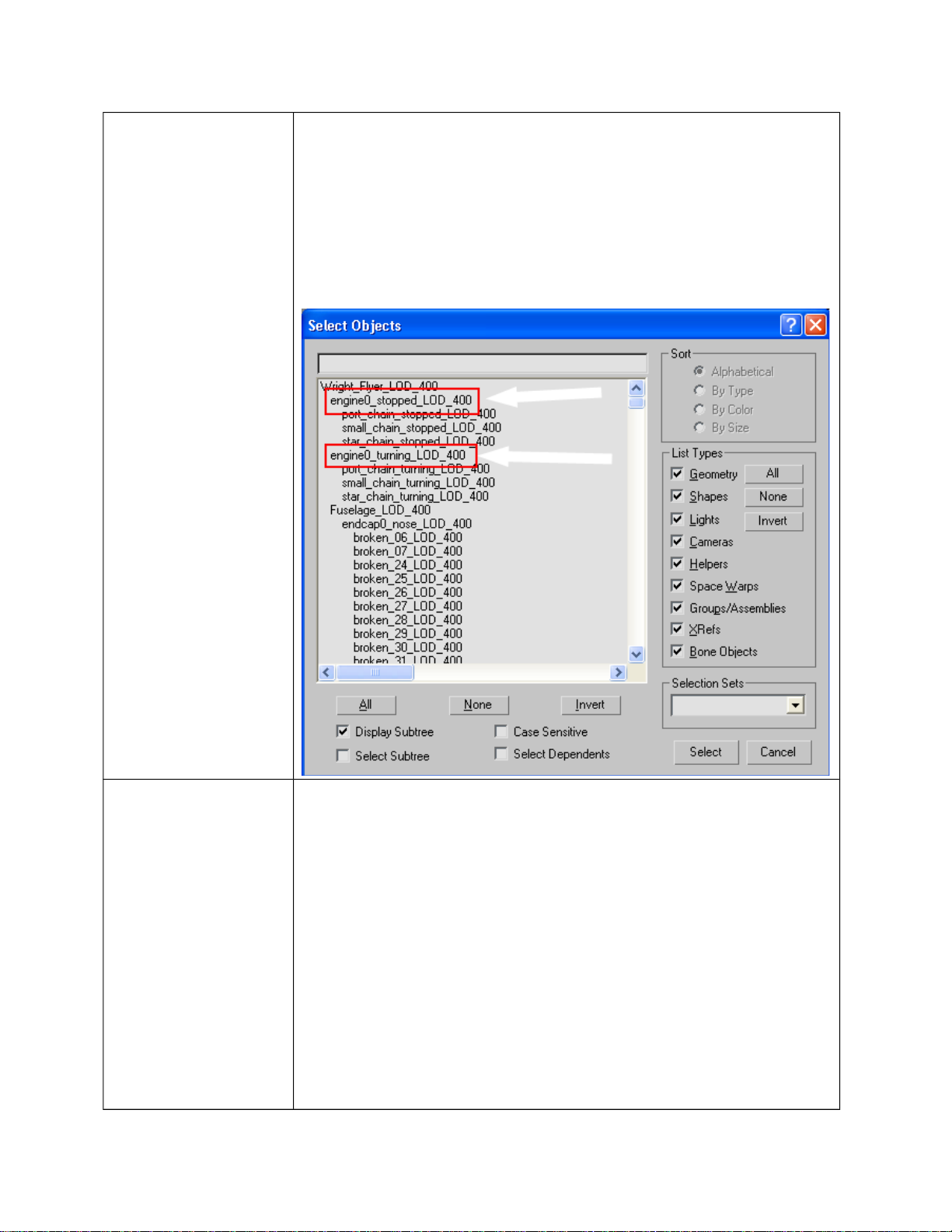
The only animated texture for the exterior model is the chain
for the Wright Flyer model. Two nodes are needed to drive the
animated chains. One node needs to be named
Engine0_Stopped. Any parts below this node are shown when
© 2003 Microsoft Corporation. All rights reserved. Page 9 of 20
Microsoft Flight Simulator 2004 gmax Aircraft Creation doc
the engine is off. The physical geometry needs no special
material or texture. The second node is named
Engine0_Turning and all geometry below this node needs a
material name of Animate_ChainSegment_16_100_. This
material must be mapped to ChainSegment0000.bmp. There
are 16 chain textures that cycle through to create the
animation.
Tires and Props
Tires retain the same naming conventions from previous
versions of Flight Simulator to show the different states of
rotation. The geometry is physically switched out through the
part name.
c_tire_still = Visible and rotating when the center tire’s
rotational speed (in rpm) is very slow.
c_tire_blurred = Visible and rotating when the center tire’s
rotational speed (in revolutions per minute (rpm)) is fast.
The same is done with l_tire_still, l_tire_blurred, r_tire_still
and r_tire_blurred.
Props use a naming convention similar to tires, except there
© 2003 Microsoft Corporation. All rights reserved. Page 10 of 20

Microsoft Flight Simulator 2004 gmax Aircraft Creation doc
are three speeds. The names have not changed. The number
following prop reflects the engine number (0-3) The prop
texture uses an 8 bit alpha channel to show transparency in the
rotating blades. Transparency is also set within the opacity
settings of the basic parameters section in order for Make
Model to process it with the correct drawing order.
prop0_still = Visible when prop 0 is very slow.
prop0_slow = Visible when prop 0 is slow.
prop0_blurred = Visible when prop 0 is fast.
Animations
A complete list of animation part names is available in the
Makemodel sdk.
Makemodel does not recognize animation on helper objects in
gmax. During the export process, the animation information
on helper objects such as a dummies or points is lost. An
object must have geometry in order for the animation to be
exported. An object with geometry can be animated and then
have its geometry deleted, leaving only a pivot. (This is
recognized through Makemodel, however, this is not
recommended.)
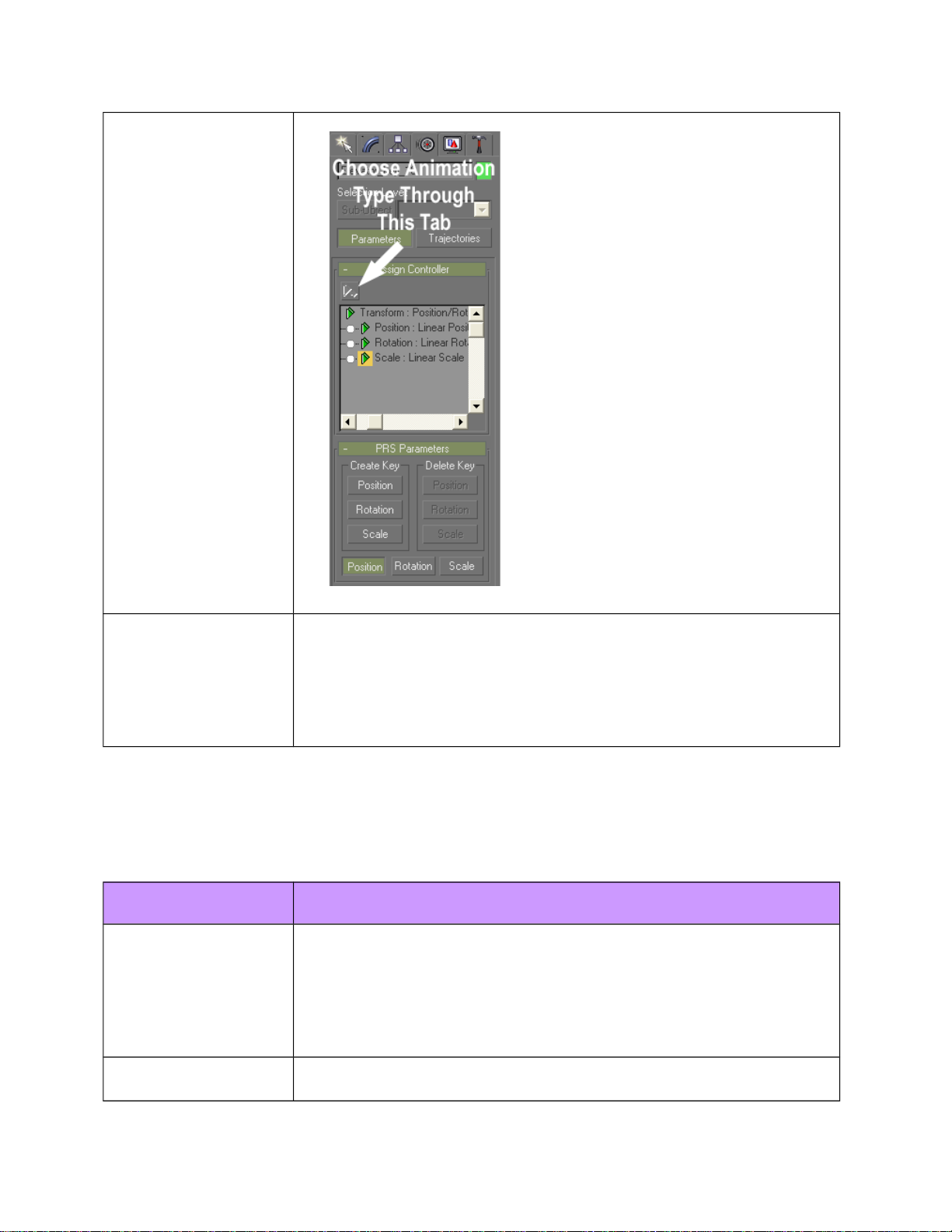
In order for an animation to be exported out of gmax, the
parameters of the animation must be set to linear. Set the
position, rotation and scale to linear for best practices. This
can be set through Motion Tab>under Parameters Tab.
© 2003 Microsoft Corporation. All rights reserved. Page 11 of 20
Microsoft Flight Simulator 2004 gmax Aircraft Creation doc
Pilots
The pilots of the new exterior models animate according to
user input. The head and legs are driven by rudder movement
and the arms are driven by the stick\yoke and throttle lever.
The geometry consists of a segmented pilot with key framed
animations.
The Interior Model
In this section, we will cover features of the interior model.
Topic Explanation
Polygon Counts
The new interior models are in the range of 9000 triangles. The
models had an increased poly count due to the scope of
animation work and because only part of the model is visible
at any one time. For best practices, we suggest staying in this
range for performance.
Textures and Virtual
Texture Sheets
The base texture name suffix (_C) has no special properties.
© 2003 Microsoft Corporation. All rights reserved. Page 12 of 20
Microsoft Flight Simulator 2004 gmax Aircraft Creation doc
We use this naming convention for organization and because
there is no damage associated with our interior model.
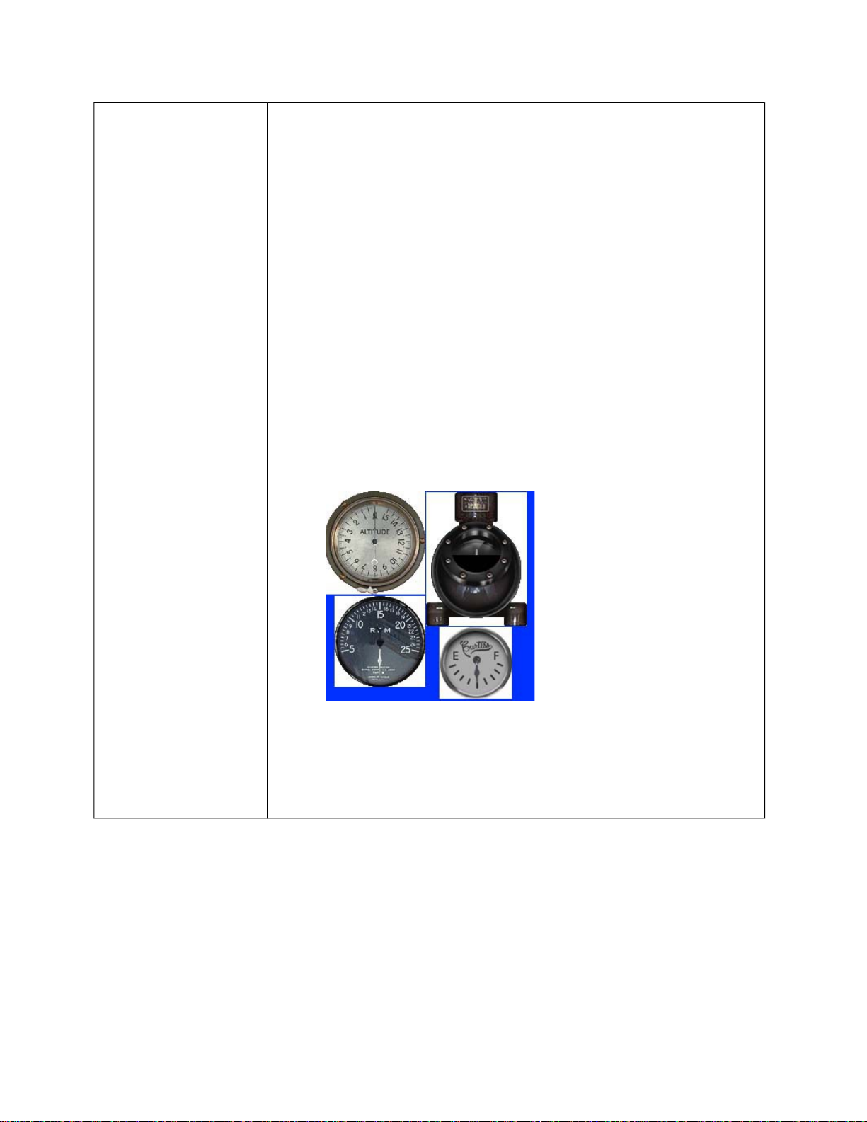
If a texture name starts with “$” or “_panel_” then the texture
is assumed to be a virtual cockpit (VC) gauge texture. This
texture serves as a specific coordinate reference on a virtual
texture sheet which maps the 2D bitmap panel gauges on the
sheet in real time. The reference to the 2D panel bitmaps is
done through the panel.cfg of the aircraft. A texture sheet
with “$” or “_panel_” is not needed once the model is exported
out of gmax.
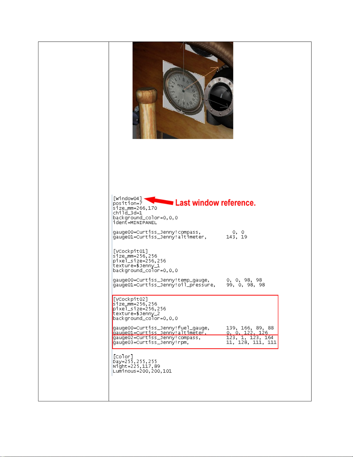
Here is a simple step by step to show how the referencing is
done.
1. Create the geometry for the gauges.
2. Create a texture sheet that shows the edges of the gauges for
precise mapping. Be sure that it has a _Panel_ prefix. FYI:
Some programs won’t let you export a $ in the name.
3. Map the texture onto the geometry as you normally would
using UVW Map and the UVW Unwrap in the UV
Coordinate Modifier stack.
© 2003 Microsoft Corporation. All rights reserved. Page 13 of 20
Microsoft Flight Simulator 2004 gmax Aircraft Creation doc
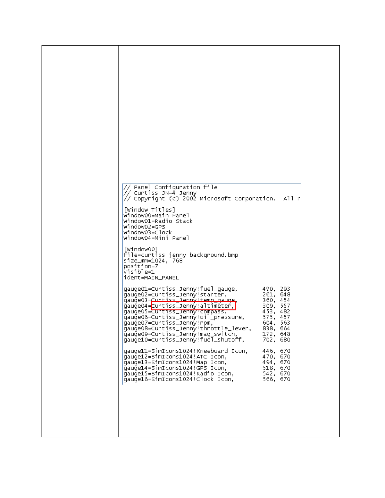
4. Once this is complete, open the panel.cfg of the aircraft in
which you are modeling. In this case, we will work with the
Curtiss Jenny.
5. Create a section for the virtual cockpit under the last window
reference section.
6. It is very important to follow the exact naming structure.
[VCockpit02]= second texture section for virtual cockpit
© 2003 Microsoft Corporation. All rights reserved. Page 14 of 20
Microsoft Flight Simulator 2004 gmax Aircraft Creation doc
Size_mm= size of texture sheet
Pixel_size= size of texture sheet
Texture= name of texture sheet ($ is the equivalent to _panel_)
Background_color= should be 0,0,0 which is transparent.
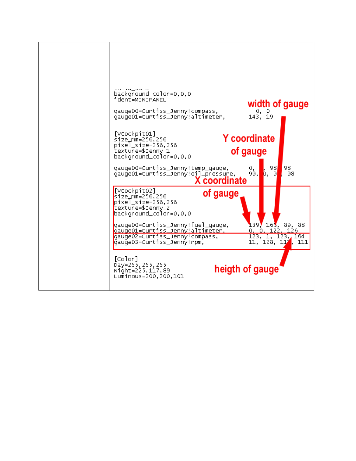
7. For the list of gauges, each gauge number needs to be unique
per texture section in the config. If the numbers repeat, they
may not draw in the simulation.
Gauge#= obtain exact name of gauge from panel section
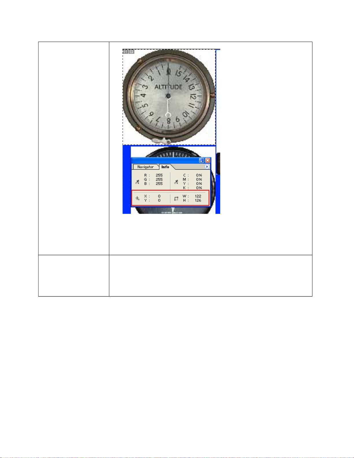
The numbers that follow the gauge name are listed in specific
order. To get this information, you will need to open the
texture in the paint program of your choice.
1
st
Number = X coordinate of top left pixel in gauge bitmap
© 2003 Microsoft Corporation. All rights reserved. Page 15 of 20
Microsoft Flight Simulator 2004 gmax Aircraft Creation doc
2
nd
Number = Y coordinate of top left pixel in gauge bitmap
3
rd
Number = width of gauge on texture sheet
4
th
Number = height of gauge on texture sheet
© 2003 Microsoft Corporation. All rights reserved. Page 16 of 20
Microsoft Flight Simulator 2004 gmax Aircraft Creation doc
When the model is exported for the sim, it will have all of the
information for the texture sheets. No _Panel_ texture sheets
are needed in the texture folder once the aircraft is in the sim.
The physical texture sheets are only for laying out the gauges.
Animating Textures
Animating texture technology was implemented for rain
effects in the virtual cockpit windshields. There is a specific
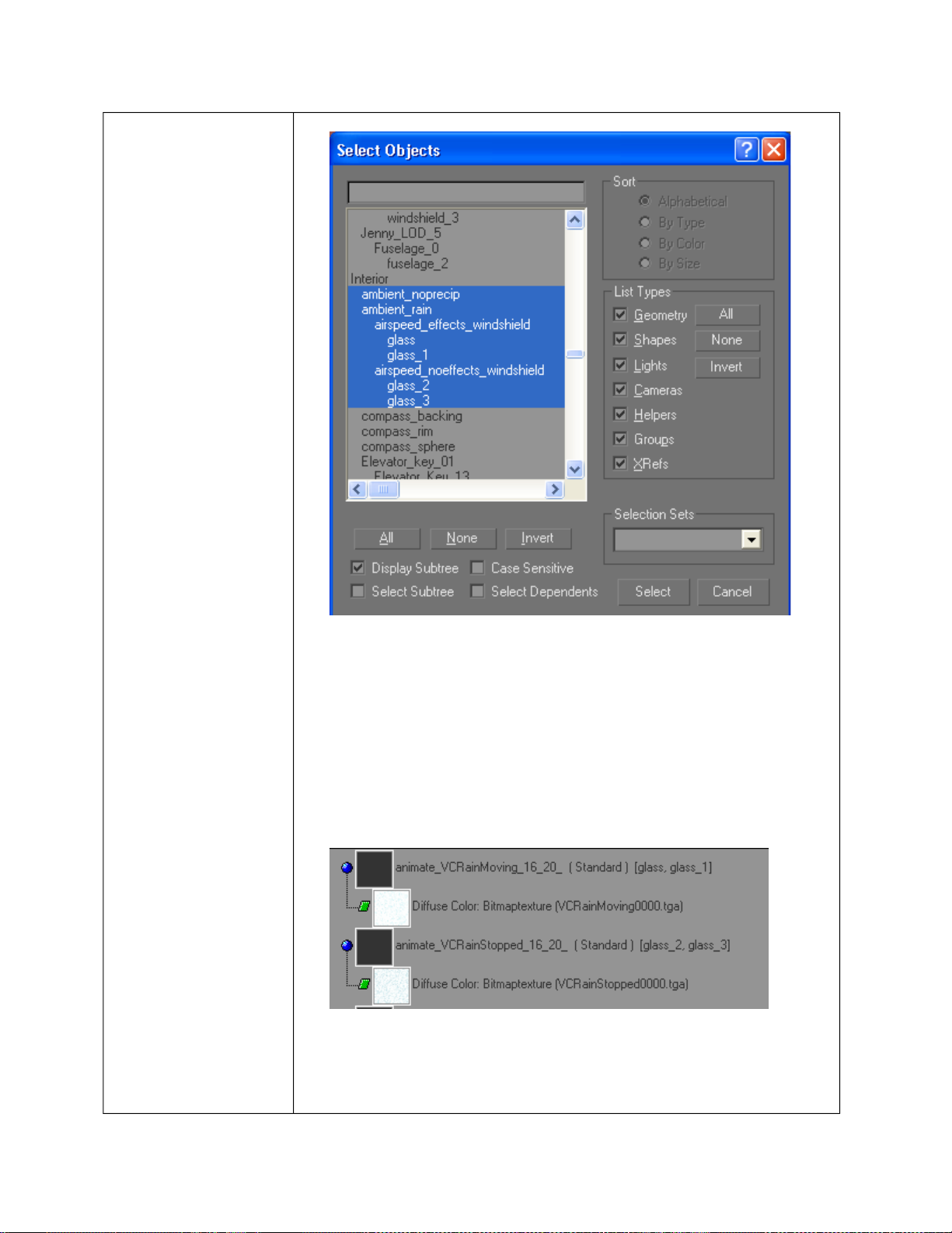
method to implementing rain in the virtual cockpits. The
hierarchy is as follows:
© 2003 Microsoft Corporation. All rights reserved. Page 17 of 20
Microsoft Flight Simulator 2004 gmax Aircraft Creation doc
There are two top nodes ambient_noprecip and ambient rain.
These nodes are dummy objects for hierarchy purposes and
are triggered by name if rain is encountered. Two subnodes,
airspeed_effects_windshield and airspeed_noeffects_windshield,
call different texture sets based on aircraft airspeed. These
objects could be the geometry that switches out. For this
exercise, the objects were hierarchical dummy objects. The
bottom objects are the glass geometry.
The physical geometry under the airspeed_effects_windshield
node needs a material name of
animate_VCRainMoving_16_20_ and must be mapped to
texture VCRainMoving0000.bmp. The material needs to be at
© 2003 Microsoft Corporation. All rights reserved. Page 18 of 20
Microsoft Flight Simulator 2004 gmax Aircraft Creation doc
0 percent opacity.
The physical geometry under the
airspeed_noeffects_windshield node needs a material name of
animate_VCRainStopped_16_20_ and must be mapped to
texture VCRainStopped0000.bmp. The material needs to be at
0 percent opacity.
Animations
A complete list of animation part names is available in the
Make Model SDK.
Make model does not recognize animation on helper objects in
gmax. During the export process, the animation information
on helper objects such as a dummies or points is lost. An
object must have geometry in order for the animation to be
exported. An object with geometry can be animated and then
have its geometry deleted leaving only a pivot. (This is
recognized through Makemodel, however, this is not
recommended.)
Special Material
Names
Animate_VCRainMoving_16_20_ = Needs 0 % opacity and
triggers specific moving rain textures.
Animate_VCRainStopped_16_20_ = Needs 0 % opacity and
triggers specific rain textures.
Eyepoints
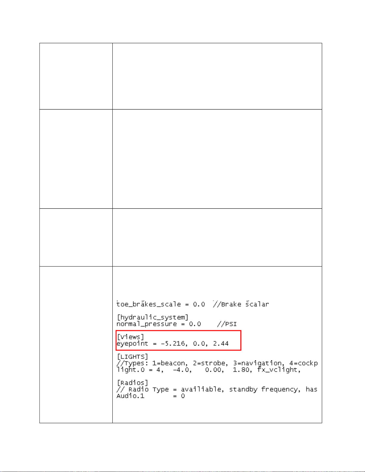
The eyepoint for the virtual cockpit is set through the aircraft
config under the view section.
The numbers are: (feet) longitudinal, lateral, vertical distance
© 2003 Microsoft Corporation. All rights reserved. Page 19 of 20
Microsoft Flight Simulator 2004 gmax Aircraft Creation doc
from reference datum.
Exporting the Model
This section covers exporting models and converting texture sheets.
Explanation Steps
Exporting the Model 1. File>Export>Name the file and select Flightsim Aircraft
Model (.mdl) for the format. Save the file to the Model folder
within the aircraft container
2. This will export the model and launch makemdl.exe.
Converting Textures 3. Convert the necessary textures through Imagetool.exe which is
available in the tools folder within gamepack
4. Open Imagetool.exe and create mipmaps (Image>Create
MipMaps).
5. Convert to specific formats (Image>Format).
6. _T textures are DXT3.
7. _D, _C, and decal textures are DXT1.
8. Prop textures are 32 bit.
9. Save the textures to the Texture folder within the aircraft
container.
© 2003 Microsoft Corporation. All rights reserved. Page 20 of 20