Panel instructions


Description

Tupolev Tu-114 was flied by a crew of 5: captain, second pilot, navigator, flight engineer and radio. We modelled all the panels, although some of them are not as complete as on the real plane - mostly because of FS limitations, but also to make panels easy to use and to understand. When you first load the aircraft, you find yourself face to the captain's panel. To switch to the navigator's and the second pilot's panels, use red arrows pointing to the right and down ("hot spots" B and C on the screenshot below). Some of the panels can be shown directly in the usual way by pressing numbers on the keyboard: ATTENTION: the panel uses metric system (except some gauges - we mention all these cases). 1ft = 0.304m, 1nm = 1.852km, 1kts=1.852km/h. 1km = 3000ft, 100km/h = 54kts, 1m/s = 200ft/min

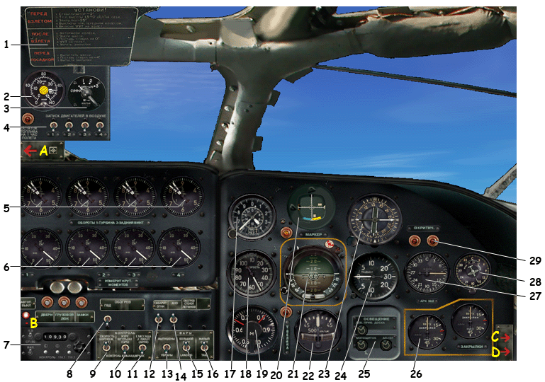
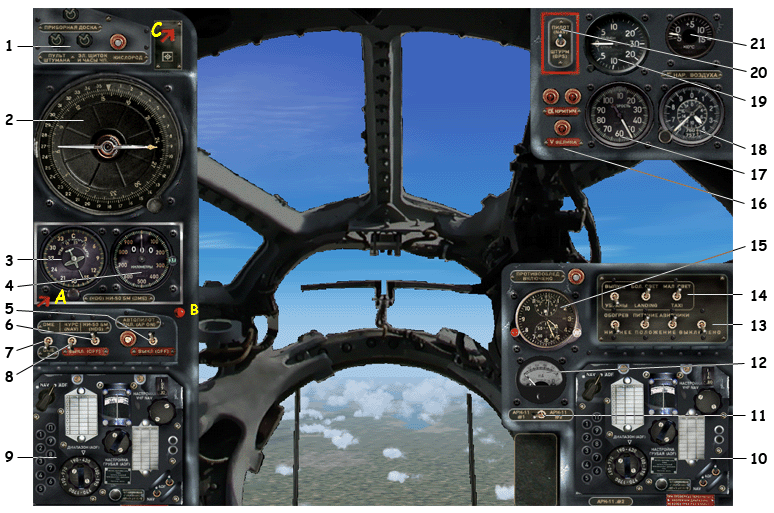
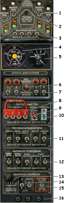
For all switches, the lower position is "OFF" and the upper position is "ON"

We recommend you turn the help messages on since some of the gauges are quite small and hardly readable.


Captain's panel

  1. headlights group. Left to right: taxi lights on/off, landing lights on/off, landing lights deploy. You can also deploy the landing lights by using the tailhook shortcut (usually Shift+T). Switch on/off the landing lights by the usual shortcut Ctrl+L
  2. autopilot led (red: "AP on") Unlike the other planes, here the "autopilot on" light is red and not green
  3. autopilot turn left/right adjust. Use this to change the cap. Don't forget to return the button to vertical position to stop turning
  4. throttle levers
  5. elevator trimmer
  6. altitude radar and a scale switch. 1 - from 0 to 120m, 2 - from 0 to 1200m. Press the button in the lower left corner to activate the radar. Use this gauge at low altitude, it indicates the right flight altitude regardless the pressure. Use the lower scale to land - the aircraft is high and you can touch the ground before you've planned. The red led to the right of the scale is altitude warning
  7. Mach-meter
  8. pitch indicator
  9. indicated airspeed (km/h x10) To the left of the indicator - three red leds: critical pitch warning and overspeed warning
  10. cabin lights group above: main panel lights, below: navigator's panel lights, flight engineer's panel lights
  11. altitude (m x100). Big arrow: hundreds of meters, small arrow: kilometers
  12. horizon. Be careful, if you inclinate too much the aircraft (more than 35� yaw), some of the engines can stop. Use the second pilot's panel to start them when airborne
  13. yaw indicator
  14. ILS indicator
  15. vertical speed (m/s)
  16. horizon
  17. radio compass The yellow led to the left of the gauge is marker warning
  18. VOR indicator
  19. flaps indicators
  20. landing gears deploy. click on the lid
  21. ILS setting panel. Three buttons in the bottom serve to test the indicator. Switch the test mode on (the leftmost switch), then press each of the three buttons and check that the arrows on the ILS indicator #14 are moving. Then switch off the test mode
  22. propellers feathering buttons Since propeller feathering is effective only when the engines are off, these buttons can also stop the engines.
  23. autopilot hold speed
  24. autopilot hold cap
  25. autopilot hold ILS
  26. open feathering buttons lid
  27. autobrake on/off
  28. fuel pressure
  29. throttle level
  30. gears state leds
  31. altimeter (feet) and pressure adjust.
  32. clock
  33. autopilot cap adjust ("TURN" handle)
  34. autopilot vertical speed adjust ("Vertical speed" handle)
  35. autopilot hold: (top to bottom) nav. hold / cap hold / vertical speed hold
  36. autopilot leds: (left to right) autopilot power switch / green led: autopilot's off / white led: autopilot's operational / red led: autopilot on / nav. hold / cap hold / altitude hold
three additional "hot spots" for switching to another panels (in yellow on the screenshot):

Second pilot's panel

  1. flight instructions notice. The text stays: "Before takeoff: set stabilizer pitch -2�, elevator trimmer 1.5-2�, flaps 25�, switch off front gear steering, deploy and switch on headlights. After takeoff: brake the wheels, retract gears, set stabilizer to 0�, retract landing lights, retract flaps. Before landing: deploy gears, set stabilizer to -4�, deploy flaps"
  2. fuel quantity indicator. One arrow per tank, the arrows are numbered
  3. fuel indicator switch. The leftmost position makes the indicator show the total fuel quantity. Other positions show the quantity per tank
  4. airborne engines start The led to the left is a warning "Fuel left for 1h of flight"
  5. turbine rpm (forward prop/rear prop)
  6. torque
  7. ILS setting panel the same as on the captain's panel. Above: red autopilot on led, three white leds: "passenger doors open", "cargo doors open", "locks". Actually all three lit together
  8. pitot heating
  9. autopilot hold speed
  10. autopilot hold cap
  11. autopilot hold ILS
  12. nav.lights
  13. beacon lights
  14. landing lights deploy (on/off)
  15. landing lights on/off
  16. taxi lights on/off
  17. altimeter (m x100)
  18. indicated airspeed (km/h x10)
  19. Mach-meter to the right: overspeed warning
  20. ILS indicator below: marker warning
  21. horizon
  22. yaw indicator
  23. radiocompass
  24. vertical speed (m/s)
  25. cabin lights
  26. flaps indicators
  27. VOR/ADF?
  28. VOR?
  29. pitch warning
"Hot spots" for switching to other panels:

Navigator's panel

To offer a comfortable view, the panel has been split into pieces and organized around the navigator's windows. On the real plane (and in the VC), the navigator sits turned left to the direction of flight and the window is at his right side.

  1. cabin lights to the right: oxygene on led
  2. precision radiocompass
  3. autopilot cap setting
  4. DME indicator
  5. autopilot on/off
  6. autopilot cap hold
  7. DME1/DME2 switch
  8. autopilot nav. hold
  9. radio panel 1 (see below)
  10. radio panel 2 (idem)
  11. switch ADF1/ADF2 for signal intensity indicator
  12. signal intensity indicator
  13. left to right: pilot's heating switch / battery switch / avionics switch / pitot heating switch
  14. lights group
  15. clock above: de-ice on led
  16. overspeed warning
  17. indicated airspeed (km/h x10)
  18. altimeter (m x100)
  19. vertical speed (m/s)
  20. navigation mode NAV/GPS switch
  21. outside temperature indicator
"hot spots":

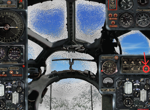
ATTENTION: don't forget to switch pilot's heating on, otherwise the windows will soon cover with ice. It will look like this:


Radio's panel

Radio's and Flight engineer's panels are simplified and can be used from within other panels.
  1. COM1 frequency setting
  2. COM1 frequency indicator
  3. COM1/COM2 switch
  4. signals indicators
  5. receivers power on indicators
  6. NAV1 frequency
  7. NAV1/ADF1 switch
  8. ADF1 indicator and setting
  9. VOR1 setting
  10. ADF1 frequency zones
  11. Morse signal ADF1/VOR1 on/off
  12. ADF signal intensity
  13. switch ADF1/ADF2 for signal intensity indicator
  14. squawk
The right side is for VOR2/ADF2, it is similar to the left one.

Flight Engineer's panel

  1. fuel pumps switches
  2. "Fuel left for 1h of flight" warning
  3. emergency fuel pumps
  4. fuel quantity indicator
  5. fuel indicator switch (see explanations for the captain's panel)
  6. stop starting engines button
  7. engines start
  8. magneto combined switches
  9. battery switch
  10. avionics switch
  11. de-ice group (left to right: exterior wing section, wing between the engines, propellers, Pitot tube)
  12. exterior lights (left to right: nav.lights, beacons, landing lights deploy, landing lights, taxi lights)
  13. autopilot speed setting (knots or Mach)
  14. autopilot speed hold (Mach / knots)
  15. autothrottle switch
  16. cabin lights

"Easy Navigation group"

if you are lost, you can still use the "easy navigation group" that is accessible from most of the panels (through a little red hotspot). It shows the principal navigation instruments and autopilot controls. These are default FS gauges and should be familiar to any simmer, so we don't stop on them. Click on the hotspot or anywhere in the background of this panel to close it.

Autopilot AP-15PS

Technical characteristics and purpose

Autopilot AP-15PS is designed to assure automatic stabilization and guidance of the aircraft

The autopilot AP-15PS assures:

Principal technical characteristics: The autopilot receives the following information:

Preparing AP-15PS

Using the autopilot

After the takeoff, use elevator trimmers to stabilize the aircraft vertical speed at 10-12m/sec. Now, switch the autopilot on.

Note that you cannot set the altitude you wish to reach. However, you can control the vertical speed with the handle "Vertical Speed" (#34) on the autopilot panel. Make sure you have the help tooltips on (in the FS settings) - the tooltip indicate the actual value for the vertical speed hold. Once you've set the desired value, switch on the vertical speed hold using the correspondent switch.

As the plane climbs to the higher altitudes, reduce the vertical speed. Be careful not to exceed 10� pitch and keep the indicated airspeed higher than 350 km/h. Tipically use the following vertical speed settings:

0-3000m (0-10000ft)10 m/s (2000 ft/min)
3000-6000m (10000-20000ft)7.5 m/s (1500 ft/min)
6000-8000m (21000-26000ft)6 m/s (1200 ft/min)
8000-10000m (26000-32000ft)3-4 m/s (600-800ft/min)
If the pitch increases reaching 10� (and/or the speed decreases), set immediately the vertical speed to 0 and fly some time horizontally to gain speed. Then set again positive vertical speed and continue climbing.

When the vertical speed is less than 1.5m/s (300 ft/min), the autopilot sets it to zero.

Use the "TURN" handle (as well the one on the autopilot panel #33 as the one on the captain's panel #3) to make coordinated turns. Setting the handle one position from the center makes the plane bank 5�.

Note that you cannot set the cap directly. Use the coordinated turn to reach the desired cap. Set the "TURN" handle to zero 5-10 degrees before you reach the cap.

There is the IAS/Mach hold possibility, but it isn't a part of standard AP-15PS features. The correspondent buttons are situated on the flight engineer's panel (#13-14)