The recommended method of creating gauges is to use the XML based system, refer to the document, Creating XML gauges. However, if the flexibility of this system does not meet your requirements, gauges can be created programmatically using C++. This document describes a number of samples that show how to do this.
Gauges.h has been updated for the release of the Flight Simulator X SDK. To use the samples and updated header file, C++, rather than C, must be used as the development language. There is also an additional sample that shows how to link an XML gauge with C++ code (see the section Creating a Gauge using XML and C++).
This SDK includes source code for several sample gauges, along with their associated resources. Use these samples to learn how to build gauges and feel free to modify them in creating your own gauges and panels. The following table shows the samples provided and a brief description.
Sample Folders and Files |
Description |
| SDKSample.vcproj | Visual Studio project file. Select this to open up the whole project in Visual Studio. |
\inc\gauges.h |
Contains the variables, macros, and other structures used by the panel and gauge system. You must #INCLUDE this file when building gauges. |
\inc\gps_info.h |
Header file used with GPS systems. |
\C-Gauge Samples\makefile |
Used to build the sample code from the command line. |
\C-Gauge Samples\SDK.h |
Define gauge constants, variables, and resources used by the sample gauges code. |
\C-Gauge Samples\SDK.cpp |
The main source file for the project. |
\C-Gauge Samples\SDK.attitude.cpp |
Contains the Attitude Indicator source and provides a sprite example. |
\C-Gauge Samples\SDK.control_surfaces.cpp |
Contains the Control surfaces source and provides a slider example. |
\C-Gauge Samples\SDK.fuel.cpp |
Contains the Fuel gauge source and provides a needle example. |
\C-Gauge Samples\SDK.fuel_selector.cpp |
Contains the Fuel Selector source and provides an icon-based example. |
\C-Gauge Samples\SDK.temperature.cpp |
Contains the Temperature display source and provides a string and icon example. |
\C-Gauge Samples\SDK.wiskey.cpp |
Contains the Whiskey compass source and provides a moving image example. |
\C-Gauge Samples\SDK.FlightMap.cpp |
Contains a simple GPS-like gauge and provides an example of implementing “owner draw” gauges. |
\C-Gauge Samples\res |
Contains the resource bitmaps used with the sample gauges. |
\C-Gauge Samples\SDK.FlightInfo.xml |
XML Gauge string. |
The goal of the sample is to create a file called SDK.gau. This is a gauge file for use by the panel system. A gauge file is a Windows DLL with the extension .gau, which is loaded by the panel system. A gauge file can contain one or more individual gauges within the panel. The panel system interacts with each gauge using the exported interface defined by the gauge header file (Gauges.h). The interface used by a gauge consists of a list of drawing elements and the exported functions used to manage the gauge. All .gau files reside within the Gauges folder. When compiled, the sample code generates a single SDK.gau containing six different gauges, each illustrating a different type.
Your gauges will need access to various resources and variables to function properly. The sample code provided with this SDK accomplishes these key definitions in three files (found in the \C-Gauge Samples folder):
SDK.h
SDK.cpp
SDK.rc
Make sure to go through the following sections carefully because they describe what’s happening within each file. Read through the sources as you go through this information as well.
When you open SDK.h you’ll first see a series of #define directives that set version information as well as some constants within the C++ preprocessor.
  #define         VERSION_MAJOR           1

  #define         VERSION_MINOR           0

  #define         VERSION_BUILD           0

  //  magic to get the preprocessor to do what we want

  #define     lita(arg) #arg

  #define     xlita(arg) lita(arg)

  #define     cat3(w,x,z)  w##.##x##.##z##\000

  #define     xcat3(w,x,z) cat3(w,x,z)

  #define     VERSION_STRING xlita(xcat3  (VERSION_MAJOR,VERSION_MINOR,VERSION_BUILD))

  #ifndef           VS_VERSION_INFO

  #define           VS_VERSION_INFO         0x0001

  #endif
Depending on which C++ compiler you are using, you may need to tweak the preprocessor information somewhat, but otherwise, you won’t need to modify the #define directives. The primary task you’ll need to accomplish inside SDK.h is to define the various resources (bitmaps) used by all the gauges you are building into the target .gau file. The following code fragment defines the constants used for resources (i.e., the resource_id) associated with the Attitude Indicator sample (SDK.attitude.cpp):
  //  Attitude Bitmaps

  //

  #define           BMP_ATTITUDE_SMALL_BACKGROUND       0x1000

  #define           BMP_ATTITUDE_SMALL_CARD1            0x1100

  #define           BMP_ATTITUDE_SMALL_MASK1            0x1101

  #define           BMP_ATTITUDE_SMALL_CARD2            0x1200

  #define           BMP_ATTITUDE_SMALL_MASK2            0x1201
The actual linking of these constants to specific .bmp files happens in SDK.rc as described later in this document. There are some rules associated with setting these constants:
    #define   BMP_1024_AIRSPEED_BACKGROUND        1000

    #define  BMP_1280_AIRSPEED_BACKGROUND        1500
    #define  BMP_ATTITUDE_SMALL_CARD1            0x1100

    #define  BMP_ATTITUDE_SMALL_MASK1            0x1101
The sample SDK.h provided defines constant values for all the bitmap resources used by the sample gauge files.
The sample resource file associates the resource_id for all the resources in all the gauges with the corresponding .bmp file. First, note that the SDK.rc file contains an include directive for SDK.h near the top:
#include “sdk.h”
You’ll need to adjust this for whatever you name your gauge header file.
Just below this, you’ll find more versioning information, along with a block entitled “StringFileInfo” as shown below:
  BEGIN

      BLOCK "StringFileInfo"

      BEGIN

          BLOCK "040904b0"

          BEGIN

              VALUE  "CompanyName", "Your Company\0"

              VALUE  "FileDescription", "Flight Simulator Gauge\0"

              VALUE  "FileVersion", VERSION_STRING

              VALUE  "LegalCopyright", "Your Copyright.\0"

              VALUE  "ProductName", "Your Product\0"

              VALUE  "ProductVersion", VERSION_STRING

          END

      END

      BLOCK "VarFileInfo"

      BEGIN

          VALUE "Translation", 0x409, 1200

      END

  END
In the string values for “CompanyName”, “FileDescription”, “LegalCopyright”, and “ProductName” replace the placeholder text with information appropriate for you. This information will appear whenever anyone checks the properties for the .gau file you create. The next section is where each resource_id defined in SDK.h gets associated with the appropriate .bmp file:
  //  Attitude Bitmaps

  //

  BMP_ATTITUDE_SMALL_BACKGROUND BITMAP      DISCARDABLE       "res\\SDK.Attitude.bg.BMP"

  BMP_ATTITUDE_SMALL_CARD1      BITMAP      DISCARDABLE       "res\\SDK.Attitude.card1.BMP"

  BMP_ATTITUDE_SMALL_MASK1      BITMAP      DISCARDABLE       "res\\SDK.Attitude.mask1.BMP"

  BMP_ATTITUDE_SMALL_CARD2      BITMAP      DISCARDABLE       "res\\SDK.Attitude.card2.BMP"

BMP_ATTITUDE_SMALL_MASK2      BITMAP      DISCARDABLE       "res\\SDK.Attitude.mask2.BMP"
You’ll need to create similar resource_id assignments for all resource files used by your gauges.
The SDK.cpp file included with this SDK enables you to manage the various gauges from a single file while still separating the individual gauge source files for easier maintenance. You don’t necessarily have to create a corresponding SDK.cpp file for your gauges, but there are some specific things you need to do within your gauge code as explained below. First, notice that SDK.cpp has #include statements for both Gauges.h and SDK.h. Make sure you include Gauges.h and SDK.h in your gauge code as well. SDK.cpp then breaks out into sections for each individual gauge, finishing up with a series of gauge table entries. Each individual gauge section contains the following coding:
  /////////////////////////////////////////////////////////////////////////////

  // Attitude

  /////////////////////////////////////////////////////////////////////////////

  #define           GAUGE_NAME        "Attitude"

  #define           GAUGEHDR_VAR_NAME gaugehdr_attitude

  #define           GAUGE_W                 100


  #include "SDK.Attitude.cpp"

  /////////////////////////////////////////////////////////////////////////////

  // Control Surfaces

  /////////////////////////////////////////////////////////////////////////////

  #define           GAUGE_NAME        "Control_Surfaces"

  #define           GAUGEHDR_VAR_NAME gaugehdr_control_surfaces

  #define           GAUGE_W                 100


  #include "SDK.Control_Surfaces.cpp"

  /////////////////////////////////////////////////////////////////////////////

  // Fuel

  /////////////////////////////////////////////////////////////////////////////

  #define           GAUGE_NAME        "Fuel"

  #define           GAUGEHDR_VAR_NAME gaugehdr_fuel

  #define           GAUGE_W                  100


  #include "SDK.Fuel.cpp"
This code is then repeated for the remaining gauges. Here’s what’s happening with each assignment: GAUGE_NAME is assigned the string that becomes the gauge’s name. This gauge name is used in the Panel.cfg file under the [windowXX] section where each gauge is defined. For the fragment above, panel.cfg would identify these gauges as:
  gauge00=SDK!Attitude, 247, 58

  gauge01=SDK!Control_Surfaces, 370, 160

gauge02=SDK!Fuel, 146, 57
GAUGEHDR_VAR_NAME is assigned the gauge name used by the Gauge Table (the module’s export table). The Gauge Table gets defined at the end of SDK.cpp. GAUGE_W is assigned a value for the number of X-axis design units used by the gauge. Note that the units used by the gauge correspond to the units used by the panel background. For example, if your panel is 1000 units and a gauge is 100 units, then that gauge will be 1/10 the size of the panel. (You can override this ratio in the Panel.cfg file.)
#include “SDK_xxx.cpp” simply includes the specific gauge code file for each gauge in the compilation.
This code repeats for each gauge within SDK.cpp. Accordingly, each of the gauge code files (SDK_xxx.cpp) ends with #undef for GAUGE_NAME, GAUGEHDR_VAR_NAME, and GAUGE_W so they’re ready to reset with new values for the next gauge.
Finally, at the end of SDK.cpp, the Gauge Table assignments are made. The Gauge Table in the sample file looks like this:
  /////////////////////////////////////////////////////////////////////////////

  // Gauge table entries

  /////////////////////////////////////////////////////////////////////////////

  GAUGE_TABLE_BEGIN()

        GAUGE_TABLE_ENTRY(&gaugehdr_attitude)

        GAUGE_TABLE_ENTRY(&gaugehdr_control_surfaces)

        GAUGE_TABLE_ENTRY(&gaugehdr_fuel)

        GAUGE_TABLE_ENTRY(&gaugehdr_fuel_selector)

        GAUGE_TABLE_ENTRY(&gaugehdr_temperature)

      GAUGE_TABLE_ENTRY(&gaugehdr_wiskey)

      GAUGE_TABLE_ENTRY(&gaugehdr_flightmap)

  GAUGE_TABLE_END()
You’ll need a GAUGE_TABLE_ENTRY for each gauge identified by GAUGEHDR_VAR_NAME, so the gauge table can export a pointer. These names must match as shown in the sample code.
Now that we’ve covered some of the basic constant and variable assignments for gauges, we’ll move on to code for the sample gauges. This SDK includes sample code for the following gauges.
Gauge |
Description |
Attitude indicator, sprite example. |
|
Control Surfaces, slider example. |
|
Simple GPS-like gauge, example of implementing “owner draw” gauges. |
|
Fuel gauge, needle example. |
|
Fuel Selector, icon example. |
|
Temperature gauge, string and icon examples. |
|
Whiskey Compass, moving image example. |
All of these files contain static image examples. The following sections describe the basic calls made within a gauge source file, pointing out the individual distinctions for each gauge type.
At the beginning of each sample gauge source file, you’ll see a code fragment like this:
  //    Set up gauge header


  char attitude_gauge_name[]    =  GAUGE_NAME;

  extern PELEMENT_HEADER        attitude_list;

extern MOUSERECT        attitude_mouse_rect[];
First, the code assigns values for the following variables used by the gauge header:
Attitude_gauge_name |
Identifies gauge name assigned in SDK.cpp |
PELEMENT_HEADER |
Identifies which gauge macro forms the background |
MOUSERECT |
Identifies mouse rectangle |
Then the code fills in values for GAUGE_HEADER_FS700, the gauge header macro. The gauge header is a structure that defines the interface used by the panel system to control the gauge DLL. You must export the gauge header to expose the gauge interface to the panel system.
Use the GAUGE_HEADER_FS700 macro to create and export the gauge header (GAUGEHDR). The GAUGE_HEADER_FS700 macro creates GAUGEHDR, filling in the unique members of the GAUGEHDR structure (see the full definition of this structure in gauges.h).
The following example shows how to use the GAUGE_HEADER_FS700 macro in code:
GAUGE_HEADER_FS700(GAUGE_W, attitude_gauge_name, &attitude_list, attitude_mouse_rect, 0, 0, 0, 0);
Here’s the syntax for the GAUGE_HEADER_FS700 macro:
#define GAUGE_HEADER_FS700(default_size_mm, gauge_name, element_list, pmouse_rect, pgauge_callback, user_data, parameters, usage)
The GAUGE_HEADER_FS700 macro has these members:
Member |
Description |
default_size_mm |
The default X axis size of the gauge in design units. This value is set as GAUGE_W in SDK.cpp. |
gauge_name |
The name of the gauge as defined in SDK.cpp as GAUGE_NAME. |
element_list |
A pointer to the first drawing element in the list of elements. |
pmouse_rect |
A pointer to the mouse rectangle drawn over the gauge. |
pgauge_callback |
A pointer to a function for the entire gauge. This will pass a message to the system. Use 0 if none. |
user_data |
A 32-bit space you can use for any data you want. Use 0 if none. |
parameters |
A field that contains a string. A pointer to this string is placed in the gauge header for use in the gauge callback function (or wherever might be appropriate). Use 0 if none. |
usage |
Not used. Use 0. |
The GAUGE_HEADER_FS700 macro creates the GAUGEHDR structure and an exported variable, gauge_header. The panel system uses the gauge_header variable to initialize each of the drawing elements. Most of the Panel API functions use gauge_header as one parameter to be passed. You will use this variable often.
Several types of aircraft system failures can be simulated. Almost all of the sample gauge source files contain code that illustrates how to set up a simulated system failure.
You’ll use the FAILURE_RECORD structure to identify the systems that—should they fail—would need to be reflected by the gauge. The structure inside Gauges.h looks like this:
  typedef     struct      FAILURE_RECORD

  {

        FAILURE_KEY       key;

        FAILURE_ACTION    action;

        PVOID             reserved;

  }

  FAILURE_RECORD,  *PFAILURE_RECORD, **PPFAILURE_RECORD;
The following code illustrates how you can build FAILURE_RECORD for a Fuel gauge:
    FAILURE_RECORD    fuel_fail[]  =

  {

      {FAIL_SYSTEM_ELECTRICAL_PANELS,   FAIL_ACTION_ZERO},

      {FAIL_GAUGE_FUEL_INDICATORS,      FAIL_ACTION_FREEZE},

      {FAIL_NONE,                       FAIL_ACTION_NONE}

 }
This code creates a FAILURE_RECORD called fuel_fail. Each FAILURE_KEY enum value identifies the system undergoing failure; its associated FAILURE_ACTION identifies what happens in the event of that failure. The final FAILURE_KEY and FAILURE_ACTION pair is always FAIL_NONE, FAIL_ACTION_NONE. The failure record can contain any number of failure keys and actions.
System failures are listed in the FAILURE_KEY enum values defined in gauges.h, and described below:
Enum values |
Description |
FAIL_NONE |
Marks the end of a failure record. |
OLD_FAIL_SYSTEM_ |
Is obsolete. Don’t use it in new gauges; use FAIL_SYSTEM_ELECTRICAL_PANELS instead. |
FAIL_SYSTEM_ENGINE |
Specifies an engine system failure. |
FAIL_SYSTEM_PITOT_STATIC |
Specifies a pitot-static system failure. |
FAIL_SYSTEM_VACUUM |
Specifies a vacuum system failure. |
FAIL_GAUGE_ADF |
Specifies an ADF gauge system failure. |
FAIL_GAUGE_AIRSPEED |
Specifies an airspeed gauge system failure. |
FAIL_GAUGE_ALTIMETER |
Specifies an altimeter gauge system failure. |
FAIL_GAUGE_ATTITUDE |
Specifies an attitude gauge system failure. |
FAIL_GAUGE_COMMUNICATIONS |
Specifies a COM1 communication gauge system failure. |
FAIL_GAUGE_FUEL_INDICATORS |
Specifies a fuel indicators gauge system failure. |
FAIL_GAUGE_GYRO_HEADING |
Specifies a gyro heading gauge system failure. |
FAIL_GAUGE_MAGNETIC_COMPASS |
Specifies a magnetic compass gauge system failure. |
FAIL_GAUGE_NAVIGATION_VOR1 |
Specifies a navigation VOR1 gauge system failure. |
FAIL_GAUGE_NAVIGATION_VOR2 |
Specifies a navigation VOR2 gauge system failure. |
FAIL_GAUGE_ TRANSPONDER |
Specifies a transponder gauge system failure. |
FAIL_GAUGE_TURN_COORDINATOR |
Specifies a turn coordinator gauge system failure. |
FAIL_GAUGE_VERTICAL_SPEED |
Specifies a vertical speed indicator gauge system failure. |
FAIL_SYSTEM_ELECTRICAL_PANELS |
Specifies a failure of the electrical panel. |
FAIL_SYSTEM_ELECTRICAL_AVIONICS |
Specifies a failure of the electrical avionics. |
FAIL_GAUGE_COMMUNICATIONS_COM2 |
Specifies a COM2 communication gauge system failure. |
You can set up a gauge element to react to one or more of the system failures shown in the FAILURE_RECORD by using one of the defined FAILURE_ACTION enum values:
Member |
Description |
FAIL_ACTION_NONE = 0 |
Takes no action. This type of failure record is typically used as the background static image for covering a gauge. |
FAIL_ACTION_FREEZE |
Freezes the gauge element at its last updated position. The element’s MODULE_VAR variable(s) will not be updated. |
FAIL_ACTION_ZERO |
Sets the element MODULE_VAR variable(s) to 0. |
FAIL_ACTION_NO_DRAW |
Erases the element and doesn't draw it again. |
Moving a little further down in the sources for the various sample gauges, you’ll see different macros being used to pass parameters between the gauge and the panel system. These macros are defined in Gauges.h, and you can use them to create various types of gauges. Let’s continue through the code to where macros first start appearing—we’ll look specifically at the sliders example and then cover all the gauge macros in detail later on.
The SDK.control_surfaces.cpp example shows how to build a gauge using sliders that move over a static image in the background. The code that follows uses the bitmaps listed in the table below as resources:
Resource Bitmap |
Resource name |
Description |
|
SDK.Control_Surfaces.Ailerons.BMP |
A slider (down pointer). |
|
SDK.Control_Surfaces.Elevator.BMP |
A slider (left pointer). |
|
SDK.Control_Surfaces.Rudder.BMP |
A slider (up pointer). |
|
SDK.Control_Surfaces.Trim.BMP |
A slider (right pointer). |
To create a slider use the MAKE_SLIDER macro:
#define     MAKE_SLIDER(      NAME,                         \

                              RES_ID,                       \

                              NEXT_LIST,                    \

                              FAILURE,                      \

                              DRAW_FLAGS,                   \

                              ASI_FLAGS,                    \

                              POSITION_X,  POSITION_Y,       \

                              SOURCE_VAR_X,  CALLBACK_X, SCALE_X,  \

                              SOURCE_VAR_Y,  CALLBACK_Y, SCALE_Y )
Fill the structure out with slider-specific information, such as the following from SDK.Control_Surfaces.cpp:
MAKE_SLIDER

  (

        cs_slider_trim,

        BMP_CS_SMALL_TRIM,

        NULL,

        0,

        IMAGE_USE_ERASE |  IMAGE_USE_TRANSPARENCY,

        0,

        20,44,

        MODULE_VAR_NONE, NULL, 0,

        ELEVATOR_TRIM, NULL, -100

  )
Refer to the MAKE_SLIDER macro for an explanation of each of these properties. The code in SDK.control_surfaces.cpp contains four separate MAKE_SLIDER macros, one for each of the different sliders used.
After the final MAKE_SLIDER macro has been defined, you’ll see the following code:
  PELEMENT_HEADER         cs_sliders_list[] =

  {

        &cs_slider_trim.header,

        &cs_slider_ailerons.header,

        &cs_slider_elevator.header,

        &cs_slider_rudder.header,

        NULL

  };
This PELEMENT_HEADER code signals the end of the series of macros and sets the order in which these different parts of the gauge appear. The display order goes from top to bottom. This works very well here since the various sliders do not overlap one another. Note that every macro you define must have an associated PELEMENT_HEADER somewhere, and it must end with a NULL. The specific code fragment above sets the order for all sliders simultaneously. In cases where sliders or other resources overlap, you could instead break these out separately. For example:
  MAKE_SLIDER

  (

         cs_slider_ailerons,

         BMP_CS_SMALL_AILERONS,

         NULL,

         0,

         IMAGE_USE_ERASE  | IMAGE_USE_TRANSPARENCY,

         0,

         95, 6,
         AILERON_DEFLECTION,  NULL, 100,

           MODULE_VAR_NONE,  NULL, 0

    )


    PELEMENT_HEADER            cs_sliders_list1[]  =

    {

           &cs_slider_ailerons.header,

           NULL

    };    \\ END OF  FIRST SLIDER MACRO


  MAKE_SLIDER(

           cs_slider_elevator,

           BMP_CS_SMALL_ELEVATOR,

           &cs_sliders_list1,

           0,

           IMAGE_USE_ERASE  | IMAGE_USE_TRANSPARENCY,

           0,

           98, 46,

           MODULE_VAR_NONE,  NULL, 0,

           ELEVATOR_DEFLECTION,  NULL, -70

    )


    PELEMENT_HEADER            cs_sliders_list2[]  =

    {

           &cs_slider_elevator.header,

           NULL

    };    \\ END OF  SECOND SLIDER MACRO


   MAKE_SLIDER

    (

           cs_slider_rudder,

           BMP_CS_SMALL_RUDDER,

           &cs_sliders_list2,

           0,

           IMAGE_USE_ERASE  | IMAGE_USE_TRANSPARENCY,

           0,

           94, 83,

           RUDDER_DEFLECTION,  NULL, 80,

           MODULE_VAR_NONE,  NULL, 0

    )


   PELEMENT_HEADER            cs_sliders_list3[]  =

    {

           &cs_slider_rudder.header,

           NULL

    };     \\ END OF  THIRD SLIDER MACRO
Note that the NEXT LIST parameter for the second slider references &cs_sliders_list1, &cs_sliders_list2, and so forth, indicating the links between each MAKE_SLIDER instance.
To set the background image for the gauge, use the MAKE_STATIC macro. You will always use this macro with every gauge you create. First, here’s the background resource used by Control_surfaces.cpp:
Resource Bitmap |
Resource name |
Description |
|
SDK.Control_Surfaces.bg.BMP |
A static background against which the sliders will move up/down/left/right. |
You’ll create the static background image with the MAKE_STATIC macro. As an example, here’s the macro structure from Gauges.h:
  #define     MAKE_STATIC(      NAME,                   \

                                RES_ID,                 \

                                NEXT_LIST,              \

                                FAILURE,                \

                                DRAW_FLAGS,             \

                                ASI_FLAGS,              \

                              POSITION_X,  POSITION_Y )\
And here’s the code fragment from Control_surfaces.cpp that uses MAKE_STATIC:
  MAKE_STATIC

  (

        cs_background,

        BMP_CS_SMALL_BACKGROUND,

        &cs_sliders_list,

        NULL,

        IMAGE_USE_TRANSPARENCY,

        0,

        0,0

  )
  PELEMENT_HEADER         cs_list     = &cs_background.header;
Refer to the MAKE_STATIC reference for descriptions of each field.
Finally, the PELEMENT_HEADER for the macro gets set to identify this image as the gauge background:
PELEMENT_HEADER cs_list = &cs_background.header;
If you look back near the top of the code, you’ll see:
EXTERN PELEMENT_HEADER cs_list;
Here, the initial assignment of cs_list identifies this specific macro with the background image for the gauge. We’re pretty much nearing the end of our sample code inside the Control_surfaces.cpp file. Let’s wrap up with a discussion of how to tell the mouse the gauge exists.
By using mouse rectangles, you can specify how a gauge will interact with the mouse pointer (i.e., mouse movement and mouse button clicks). For example, you can change the cursor or display a ToolTip as the mouse enters the area you've defined as a mouse rectangle; you can also trigger a simulation event or execute a callback function. Note that the mouse rectangle you define is specific to the gauge itself—it works off the gauge coordinates, not the panel background coordinates. This allows you to move the gauge around the panel, while keeping the mouse rectangle intact.
To define a mouse rectangle, you use a combination of the mouse definition macros, as shown in the following code example from the SDK.control_surfaces.cpp file:
  MOUSE_BEGIN( cs_mouse_rect, HELP_NONE, 0, 0 )

    MOUSE_PARENT( 0,0,44,94, HELPID_GAUGE_PITCH_TRIM)

    MOUSE_PARENT( 60,0,76,16, HELPID_GAUGE_ROLL_TRIM)

    MOUSE_PARENT( 82,16,32,62, HELPID_GAUGE_PITCH_TRIM)

    MOUSE_PARENT( 60,78,76,16, HELPID_GAUGE_YAW_TRIM)

  MOUSE_END
MOUSE_BEGIN, MOUSE_PARENT, and MOUSE_END are all macros you can use when defining mouse rectangles. You should look inside the Gauges.h file to get a detailed understanding of how these macros are defined. MOUSE_BEGIN uses the following parameters.
Parameter |
Description |
name |
Contains the name of the MOUSERECT you’ve assigned to the rectangle. |
helpid |
Contains the Help ID of the ToolTip message you want to appear when a mouse cursor enters the rectangle. For foreign versions, the Help IDs point to localized strings. There is currently no way to add more ToolTip ID’s. |
x, y |
Specifies the upper-left corner of the rectangle. For MOUSE_BEGIN, this value will always be 0, 0. |
MOUSE_END ends the definition of the rectangle. You can also create rectangles within rectangles by using the capabilities of MOUSE_PARENT_* and MOUSE_CHILD_*.
You can also define sub-rectangles within the gauge rectangle using the MOUSE_PARENT and MOUSE_PARENT_BEGIN macros. Both of these macros use the following parameters.
Parameter |
Description |
x, y |
Specifies the X and Y position from the 0,0 position of the gauge. |
w, h |
Specifies the width and height of the rectangle. |
Help ID |
Specifies the Help ID of the ToolTip text to display for the rectangle. For foreign versions, the Help IDs point to localized strings. There is currently no way to add more ToolTip IDs. |
The only difference between MOUSE_PARENT and MOUSE_PARENT_BEGIN is that MOUSE_PARENT includes both MOUSE_PARENT_BEGIN and MOUSE_PARENT_END.
The MOUSE_CHILD_EVENT macro defines a sub-rectangle of the rectangle created by MOUSE_PARENT_BEGIN. Using this macro, you can generate panel system events (such as KEY_SMOKE_TOGGLE, which toggles the smoke system ON/OFF) from a mouse rectangle. This macro uses the following syntax:
MOUSE_CHILD_EVENT(x, y, w, h, cursor, mouse_flags, event_id)
MOUSE_CHILD_EVENT uses the following parameters.
Parameter |
Description |
x, y |
Specifies the upper-left corner of the rectangle. |
w, h |
Specifies the width and height of rectangle. |
Specifies the cursor shown when the mouse is in the mouse rectangle. This parameter can be set to one of the following:
|
|
Specifies under what conditions the event will be generated. It can be set to one of the following values:
|
|
event_id |
Specifies the simulation event to be sent by the mouse event. For a complete list of events, see the associated file EventIDs documentation. |
The following is an example of mouse rectangle setup code that generates the KEY_FLAPS_DECR and KEY_FLAPS_INCR events:
  MOUSE_BEGIN(mouse_rect, HELPID_B737_FLAPS, 0, 0)

  MOUSE_CHILD_EVENT(0,0,44,85, CURSOR_DOWNARROW,  MOUSE_LEFTSINGLE, KEY_FLAPS_DECR)

  MOUSE_CHILD_EVENT(44,0,44,85, CURSOR_UPARROW,  MOUSE_LEFTSINGLE, KEY_FLAPS_INCR)

MOUSE_END You can use the MOUSE_CHILD_FUNCT macro to specify a callback function when an event specified by the mouse_flags parameter is triggered. You will need to define the callback function with the mouse_child_funct function. The trigger_key_event and panel_window_toggle functions are often used in the mouse event callback functions. For information on all the functions available, refer to the C++ Gauges Function Reference section. The syntax for MOUSE_CHILD_FUNCT is as follows:
MOUSE_CHILD_FUNCT(x, y, w, h, cursor, mouse_flags, function)
MOUSE_CHILD_FUNCT uses the following parameters:
Parameter |
Description |
x, y |
Specifies the upper-left corner of the rectangle. |
w, h |
Specifies the width and height of the rectangle. |
cursor |
Specifies the type of cursor that is shown when the mouse is in the mouse rectangle. |
mouse_flags |
Specifies under what mouse conditions the callback function will be executed. |
function |
Specifies the callback function executed by the mouse event. You must define this function using mouse_child_funct. |
Here’s a code snippet showing how you would use the MOUSE_CHILD_FUNCT macro to designate a callback function:
  MOUSE_BEGIN( fuel_selector_mouse_rect,  HELPID_GAUGE_FUEL_SELECTOR, 0, 0 )

        MOUSE_CHILD_FUNCT(  0,0,39,48, CURSOR_HAND, MOUSE_LEFTSINGLE, fuel_selector_mouse_cb )

MOUSE_END The SDK.FlightMap.cpp file contains the following code example of how you can use dynamic ToolTips (that is, ToolTips where the text changes depending on the state of the gauge):
MOUSE_TOOLTIP_TEXT_STRING ("Ground Speed: %1!d! knots, Track: %2!d!°, Next Waypoint: %3!s!, Distance: %4!.1f! nm", GPS_Args)
The first argument in MOUSE_TOOLTIP_TEXT_STRING above is the ToolTip text. Note that changeable parts of the ToolTip text are specified by constructs such as “%1!d!”. These constructs always start with a percent sign (“%”), followed by the argument number (in the arguments array, GPS_Args). The argument number starts at 1 and increases sequentially. This argument number is followed by a formatting argument. The formatting argument is placed between exclamation marks (“!”), for example, !d!. This formatting argument is similar to the arguments of the printf function (from the C Standard Library), where “d” (in the formatting argument) prints an integer and “f” (in printf) prints a floating point number. GPS_Args, in the code example above, is the name of the argument’s array. The code below, taken from the sample file, illustrates how this array is defined.
  MOUSE_TOOLTIP_ARGS (GPS_Args)

        MOUSE_TOOLTIP_ARG  (MODULE_VAR_NONE, 0, NULL, NULL, NULL, GPSARG_Get_GroundSpeed, NULL, NULL)

        MOUSE_TOOLTIP_ARG  (MODULE_VAR_NONE, 0, NULL, NULL, NULL, GPSARG_Get_Track, NULL, NULL)

        MOUSE_TOOLTIP_ARG  (MODULE_VAR_NONE, 0, NULL, NULL, NULL, NULL, NULL, GPSARG_Get_WP_ID)

        MOUSE_TOOLTIP_ARG  (MODULE_VAR_NONE, 0, NULL, NULL, NULL, GPSARG_Get_WP_Distance, NULL, NULL)

  MOUSE_TOOLTIP_ARGS_END
Arguments in the MOUSE_TOOLTIP_ARG macro follow this order:
All functions have the same argument but have a return result of different types. The arguments are:
These functions can return: a numeric value, used together with numeric formats “d” or “f”; the id value used as a HELPID enum; or a string value used with “s” format. For details, see the SDK.FlightMap.cpp example.
Once you’ve finished defining the mouse rectangles for your gauges, you can compile the files and start the process of testing, debugging, and rebuilding—until you wind up with gauges you’re happy with. You can create gauges using the Visual C++ compiler, version 4.0 or later. The process used for compiling gauges with other compilers should be similar. To compile and view your new gauges, complete these steps:
Gauges have access to information about the simulation state. You can access state information through a set of token variables. The state information provided to the token variables depends on the aircraft’s .air file. Each .air file provides access to different token variables. For example, the Cessna 182 provides access to GROUND_ALTITUDE, as does every other aircraft. The Cessna 182, however, doesn’t provide access to the TURB_ENGINE_1_VIBRATION variable because the Cessna 182’s .air file specifies that this aircraft has a reciprocating engine, not a turbine engine. Therefore, it’s important to make sure that the .air file you’re using for your aircraft and gauges supports the token variables those gauges require.
Each token variable returns a specific type of data. The following structure shows how the UNIVERSAL_VAR variable is defined and the types that could be returned:
  typedef union UNIVERSAL_VAR {

      FLOAT64 n; // any number.

      BOOL b; // any boolean

      ENUM e; // any enumerated value

      FLAGS f;// any flags field

      PVOID p;// any pointer

      VAR32 d;// any binary coded decimal

      VAR32 o;// any binary coded octal

  } UNIVERSAL_VAR, *PUNIVERSAL_VAR, **PPUNIVERSAL_VAR;
The table in the Token Variables document lists the module variable name and specifies which UNIVERSAL_VAR union member to use with each variable.
You can access token variables in three ways:
    typedef struct MODULE_VAR

    {

        GAUGE_TOKEN id;

        PVOID var_ptr;

        VAR_TYPE var_type;

        UNIVERSAL_VAR var_value;

        UNIVERSAL_VAR var_old;

    } MODULE_VAR, *PMODULE_VAR,  **PPMODULE_VAR;
lookup_var(PMODULE_VAR module_var )After the lookup_var function is called, the value of a MODULE_VAR variable is stored in the var_value member of the structure.
Important: Token variables are read-only. Any attempt to set these variables through the var_ptr variable may result in unpredictable behavior.
The following code example shows how the MODULE_VAR variable is used. Note that this is a callback function and, in this specific example, it is for a sprite element.
  MODULE_VAR  attitude_bank     =  { ATTITUDE_INDICATOR_BANK_DEGREES };


  FLOAT64     flight_director_bank_cb(  PELEMENT_SPRITE pelement )

  {

        lookup_var(&attitude_bank);


        // Offset by attitude card's bank

        return attitude_bank.var_value.n -  pelement->source_var_0.var_value.n;

} Each of the Gauge macros makes use of the drawing elements available. These drawing elements are part of the macro definition in Gauges.h. Here is each macro and its associated element.
Macro |
Drawing Element |
MAKE_STATIC |
ELEMENT_STATIC_IMAGE |
MAKE_NEEDLE |
ELEMENT_NEEDLE |
MAKE_STRING |
ELEMENT_STRING |
MAKE_SLIDER |
ELEMENT_SLIDER |
MAKE_ICON |
ELEMENT_ICON |
MAKE_MOVING |
ELEMENT_MOVING_IMAGE |
MAKE_SPRITE |
ELEMENT_SPRITE |
Each macro has twelve shared data elements, which aren't included in the declaration of each structure. Instead, a #define HEADER is present that, when expanded, produces the twelve data members. The following code examples show the drawing element ELEMENT_NEEDLE before and after expansion. Before expansion:
  typedef struct ELEMENT_NEEDLE

  {

      HEADER;

      'Needle-specific data members

  };
After expansion:
  typedef struct ELEMENT_NEEDLE

  {

      ELEMENT_TYPE_ENUM element_type;

      ID resource_id;

      PIXPOINT position;

      PIXPOINT previous_position;

      PIXPOINT ofs;

      PGAUGEHDR gauge_header;

      struct ELEMENT_HEADER previous_element;

      struct ELEMENT_HEADER next_element;

      PFAILURE_RECORD failure_systems;

      FLAGS image_flags;

      FLAGS aircraft_special_instrumentation;

      FLAGS reserved;

      'Needle-specific data members.

}; The first twelve data members are the same for all the drawing element structures. The data members are described in the following table.
Member |
Description |
element_type |
Specifies the element type. Set this member to be one of the following elements:
|
resource_id |
Specifies the resource ID of an 8-bit or 24-bit bitmap resource. All element types, with the exception of ELEMENT_STRING (which ignores this value), use this value. |
position |
Specifies the point that the drawing element pivots around. This value is used by ELEMENT_NEEDLE and ELEMENT_SPRITE and ignored by the other elements. |
previous_position |
Specifies the previous position of the element relative to the gauge position. Used by the panel system. This value is ignored during initialization. |
ofs |
Specifies an offset (pivot point) for an element to rotate around. This value is used by ELEMENT_NEEDLE and ELEMENT_SPRITE and ignored by the other elements. |
gauge_header |
Points to the gauge header file. |
previous_element |
Points to the previous element. This value is set by the panel system. This value is ignored during initialization. |
next_element |
Points to a list of graphical elements. The elements are drawn after the current element. This value is used to determine the drawing order of all the elements in your gauge. |
failure_systems |
Points to a FAILURE_RECORD list. This list defines how an element will react during simulated aircraft system failure. |
image_flags |
Specifies how the element image will be rendered, with one or more DRAW_FLAGS. |
aircraft_special_instrumentation |
Specifies the Aircraft Special Instrumentation flags. |
reserved |
This value is reserved and must be set to 0. |
Each drawing element structure has one or more MODULE_VAR members. You can initialize these members to one of the token variable values. Call the function element_install or element_list_install to initialize the MODULE_VAR element(s). The element_update or element_list_update function can be used to update the contents of the MODULE_VAR. The elements themselves use the MODULE_VAR information at render time to determine in what state they'll be rendered.
Graphical elements can use the MODULE_VAR structure member to determine the state in which the element will be rendered. Sometimes, however, MODULE_VAR may not be a useful value. You can get around this problem by using callbacks. For each of the MODULE_VAR structures listed in the element structure, you can set an associated PMODULE_VAR_CB pointer. The pointer points to a callback function that you can use to set the variable to a useful value. The callback function is called by the panel system after the variable has been updated from the simulation state information. The callback function is generally used to normalize or scale the MODULE_VAR value into a valid range. You can also use the callback function to convert enumerated values, interpret a flag's variable, and so on.
For example, the following code uses a callback routine to clip the airspeed to a useful range that can be used by the airspeed gauge. All elements use the same style callback routine in which the argument to the function acts as a pointer to that element.
  FLOAT64  convert_var_aspeed(PMODULE_VAR var)

  {

      if (var->var_value.n > GAUGE_MAX_AIRSPEED)

      var->var_value.n = GAUGE_MAX_AIRSPEED;

      if (var->var_value.n < 60)

      var->var_value.n = 60;

      return var->var_value.n;

  }
You can set any callback pointer to NULL so that no call will occur. Any assignments to the MODULE_VAR in a callback routine are discarded. The final value set in MODULE_VAR is the return value of the callback function.
In code, the drawing elements are organized (using the next_element data member) in a tree structure (the element list). This element list defines the drawing order of the gauge elements:
You don't need to set the previous_element pointer. This pointer is initialized by the panel system when the gauge is initialized.
This section describes each of the following gauge macros:
The MAKE_STATIC macro draws the simplest type of graphical element. Use MAKE_STATIC to draw an image that never changes.
Here’s the macro structure from Gauges.h:
  #define     MAKE_STATIC(      NAME,                   \

                                RES_ID,                 \

                                NEXT_LIST,              \

                                FAILURE,                \

                                DRAW_FLAGS,             \

                                ASI_FLAGS,              \

                                POSITION_X,  POSITION_Y )\
And here’s the code fragment from Control_surfaces.cpp that uses MAKE_STATIC:
  MAKE_STATIC

  (

        cs_background,

        BMP_CS_SMALL_BACKGROUND,

        &cs_sliders_list,

        NULL,

        IMAGE_USE_TRANSPARENCY,

        0,

        0,0

  )
  PELEMENT_HEADER         cs_list     = &cs_background.header;
The following table explains the different fields in MAKE_STATIC.
Field |
Sample Code |
Description |
NAME |
cs_background |
Contains the unique name you assign to the macro—this specific name applies to the static background image. |
RES_ID |
BMP_CS_SMALL_BACKGROUND |
Contains the name of the resource file used by the macro as identified earlier by SDK.h. |
NEXT_LIST |
&cs_sliders_list |
Sets the order in which parts of the gauge get drawn. The example identifies the sliders. |
FAILURE |
NULL |
References a FAILURE_RECORD or NULL. |
DRAW_FLAGS |
IMAGE_USE_TRANSPARENCY |
One or more DRAW_FLAGS. |
ASI_FLAGS |
0 |
Specifies the Aircraft Special Instrumentation flags. |
POSITION_X, POSITION_Y |
0,0 |
Specifies the X,Y coordinates, in display units relative to the background image (i.e., static image), at which to initially place the bitmap. Since this is the background image, always set the X,Y coordinates to 0,0. |
Use MAKE_NEEDLE to draw an image that pivots around a specific point in another image. MAKE_NEEDLE supports transparency and nonlinear gauges. For MAKE_NEEDLE, POS (position) is the center of rotation in the background image; OFS (offset) is the center of rotation in the needle image.
Here’s the macro structure from Gauges.h:
  #define     MAKE_NEEDLE(      NAME,                               \

                                RES_ID,                             \

                                NEXT_LIST,                          \

                                FAILURE,                            \

                                DRAW_FLAGS,                         \

                                ASI_FLAGS,                          \

                                BKND_POSITION_X,  BKND_POSITION_Y,   \

                                NDL_POSITION_X,  NDL_POSITION_Y,     \

                                SOURCE_VAR,  CALLBACK,               \

                                NONLINEARITY_TABLE,                 \

                                MAX_DEG_PER_SEC  )                   \
And here’s the code fragment from SDK.fuel.cpp that uses this macro:
  MAKE_NEEDLE

  (

        fuel_needle,

        BMP_FUEL_SMALL_NEEDLE,

        NULL,

        fuel_fail,

        IMAGE_USE_TRANSPARENCY  | IMAGE_USE_ERASE,

        0,

        150, 150,

        6, 12,

        FUEL_QUANTITY_CENTER,fuel_needle_cb,

        fuel_nonlinearity,

        6

  )
The following table explains the different fields in MAKE_NEEDLE.
Field |
Sample Code |
Description |
NAME |
fuel_needle |
Contains the unique name you assign to the macro—this specific name applies to the static background image. |
RES_ID |
BMP_FUEL_SMALL_NEEDLE |
Contains the name of the resource file used by the needle as identified earlier by SDK.h. |
NEXT_LIST |
NULL |
Sets the order in which parts of the gauge get drawn. |
FAILURE |
fuel_fail |
References a FAILURE_RECORD or NULL. |
DRAW_FLAGS |
IMAGE_USE_TRANSPARENCY | IMAGE_USE_ERASE |
One or more DRAW_FLAGS. |
ASI_FLAGS |
0 |
Specifies the Aircraft Special Instrumentation flags. |
BKND_POSITION_X, BKND_POSITION_Y |
150, 150 |
The X and Y coordinates on the background image around which the needle rotates. |
NDL_POSITION_X, NDL_POSITION_Y |
6, 12 |
The X and Y coordinates of the needle itself around which the needle revolves—the fix point of the needle. In general, bitmaps for needles should be drawn horizontally. |
SOURCE_VAR |
FUEL_QUANTITY_ |
Token Variable used to drive the needle. You can enter MODULE_VAR_NONE if you want to set your variable values. |
CALLBACK |
fuel_needle_cb |
Callback function associated with the needle. |
NONLINEARITY_ |
fuel_nonlinearity |
Name of the non-linearity table used by the needle. |
MAX_DEG_PER_SEC |
6 |
Determines the refresh rate for the macro. Gauges are refreshed 18 times per second, so a value of 0 means update every cycle; a value of 6 means update every third of a second. You trade off gauge display quality versus frame rate—lower numbers give smoother display but worse frame rate. |
In some cases, you might want a needle to move in a nonlinear manner. For example, an airspeed gauge sometimes shows a greater angle between 0 and 50 knots than the angle between 100 and 150 knots. You can specify this behavior by using a non-linearity table. A non-linearity table is an array of NONLINEARITY structures. Each element in the array represents a discrete point on a gauge where the value is known. For example, your gauge might show airspeed as values from 0 to 160 knots, with tick marks every 20 knots. You could create an entry for each tick, filling in the pt and value member variables of the NONLINEARITY structure.
A NONLINEARITY structure uses the following members.
Member |
Description |
pt |
Specifies the X, Y point in the background bitmap. |
value |
Contains the readout of the gauge at that point. |
degrees |
Used internally by the panel system: do not use. Must be set to 0. |
In SDK.Fuel.cpp, the linearity table deals with the fuel quantity, which ranges from 0 to 75. Here’s the non-linearity table it uses:
  NONLINEARITY   fuel_nonlinearity[] =

  {

        {{30, 182},  0,  0},

        {{119, 47}, 25,  0},

        {{246, 93}, 50,  0},

        {{241, 221}, 75,  0}

  };
At runtime, the value of the needle is examined and the angle to be drawn is interpolated from the non-linearity table. Values are listed in the table as they appear on the gauge (clockwise around the face). If gauge values increase when rotating clockwise, values in the non-linearity table will start at the minimum and increase. If gauge values decrease when rotating clockwise, then values in the table will start with the maximum and decrease.
Use MAKE_STRING to display text on a gauge. MAKE_STRING is particularly useful when you have a string that changes as the gauge is updated; the string can be automatically updated by setting up the MODULE_VAR elements and using callback functions. Using MAKE_STRING, you can specify the font name, weight, and the background and foreground colors of the text. You can also specify a highlight text color to use when the string is selected.
Here’s the macro structure from Gauges.h:
  #define       MAKE_STRING(  NAME,                                          \

                                           NEXT_LIST,                        \

                                           FAILURE,                          \

                                           DRAW_FLAGS,                       \

                                           ASI_FLAGS,                        \

                                           POSITION_X,  POSITION_Y,           \

                                           SIZE_X,  SIZE_Y,                   \

                                           NUM_CHARS,                        \

                                           SOURCE_VAR_1,                     \

                                           SOURCE_VAR_2,                     \

                                           SOURCE_VAR_3,                     \

                                           FORECOLOR,                        \

                                           BACKCOLOR,                        \

                                           HILITECOLOR,                      \

                                           FONT_NAME,                        \

                                           FONT_WEIGHT,                      \

                                           FONT_CHARSET,                     \

                                           FONT_SIZE,                        \

                                           DRAW_TEXT_FLAGS,                  \

                                           HILITE_LIST,                      \

                                           CALLBACK)                         \
Here’s the code fragment from SDK.Temperature.cpp that uses the MAKE_STRING macro:
   MAKE_STRING

    (

           temperature_string,

           NULL,

           temperature_fail,

           IMAGE_USE_ERASE  | IMAGE_USE_BRIGHT,

           0,

           28, 9,

           60, 29,

           3,

           TOTAL_AIR_TEMP,

           DISPLAY_UNITS,

           MODULE_VAR_NONE,

           RGB(255,0,0),

           RGB(0,0,0),

           RGB(92,92,92),

           GAUGE_FONT_DEFAULT,

           GAUGE_WEIGHT_DEFAULT,

           GAUGE_CHARSET,

           0,

           DT_CENTER |  DT_VCENTER | DT_SINGLELINE,

           NULL,

           temperature_string_cb

    )
The following table explains the different fields in MAKE_STRING.
Field |
Sample Code |
Description |
||||||||||||||||||||||||||||||||
NAME |
temperature_string |
Contains the unique name you assign to the macro—this specific name applies to the static background image. |
||||||||||||||||||||||||||||||||
RES_ID |
NULL |
Contains the name of the resource file used by the macro. |
||||||||||||||||||||||||||||||||
NEXT_LIST |
NULL |
Sets the order in which parts of the gauge are drawn. |
||||||||||||||||||||||||||||||||
FAILURE |
temperature_fail |
References a FAILURE_RECORD or NULL. |
||||||||||||||||||||||||||||||||
DRAW_FLAGS |
IMAGE_USE_ERASE | IMAGE_USE_BRIGHT |
One or more DRAW_FLAGS. |
||||||||||||||||||||||||||||||||
ASI_FLAGS |
0 |
Specifies the Aircraft Special Instrumentation flags. |
||||||||||||||||||||||||||||||||
POSITION_X, POSITION_Y |
28, 9 |
Specifies the X and Y coordinates on the background image where you want the text to display. |
||||||||||||||||||||||||||||||||
SIZE_X, SIZE_Y |
60, 29 |
Defines the height and width of each character. |
||||||||||||||||||||||||||||||||
NUMCHARS |
3 |
Specifies the number of characters to use in the string. The optimal font size is calculated using the information passed to the macro. |
||||||||||||||||||||||||||||||||
SOURCE_VAR_1 |
TOTAL_AIR_TEMP |
Contains the token variable used to update the string. The string can contain numbers, characters, or both. If you want to set your variable values, enter MODULE_VAR_NONE. |
||||||||||||||||||||||||||||||||
SOURCE_VAR_2 |
DISPLAY_UNITS |
Used to look up multiple token variables to update the string. (e.g., Hours, Minutes, Seconds). Sequence them inside the callback function. |
||||||||||||||||||||||||||||||||
SOURCE_VAR_3 |
MODULE_VAR_NONE |
Contains the token variable used to update the string. |
||||||||||||||||||||||||||||||||
FORECOLOR |
RGB(255,0,0), |
Defines the foreground (or daylight) color of the string display. |
||||||||||||||||||||||||||||||||
BACKCOLOR |
RGB(0,0,0), |
Defines the background color of the string display. |
||||||||||||||||||||||||||||||||
HILITECOLOR |
RGB(92,92,92), |
Defines the highlight color for the selected area. |
||||||||||||||||||||||||||||||||
FONT_NAME |
GAUGE_FONT_DEFAULT |
Contains the font name of the string. For more information, see “Defining the Font Type” below. |
||||||||||||||||||||||||||||||||
FONT_WEIGHT |
GAUGE_WEIGHT_DEFAULT |
Contains the font weight of the string. (The sample code sets the value of GAUGE_WEIGHT_DEFAULT to FW_NORMAL.)
|
||||||||||||||||||||||||||||||||
FONT_CHARSET |
GAUGE_CHARSET |
Specifies the font character set for the string. A list of valid values can be found in the CreateFont Win32 API. |
||||||||||||||||||||||||||||||||
FONT_SIZE |
0 |
Specifies the font size for the string. A value of zero (0) means scale so that NUMCHARS capital W's fit into SIZE_X. A non-zero FONT_SIZE means fixed height. |
||||||||||||||||||||||||||||||||
DRAW_TEXT_ |
DT_CENTER | DT_VCENTER | DT_SINGLELINE |
Sets how to draw the text. There are three valid entries:
|
||||||||||||||||||||||||||||||||
HILITE_LIST |
NULL |
Lists gauge selection states. For a table listing all gauge selection states, see Selecting a String by KEY_EVENT below. (You can also find examples of gauge selection states in Gauges.h.) |
||||||||||||||||||||||||||||||||
CALLBACK |
temperature_string_cb |
Updates the string. The callback function updates the string member variable. The string member variable is the character string data that's used to render this drawing element. |
To define the font type you must place #define statements (after the initial #include) in your gauge code. For example, SDK.Temperature.cpp looks like this:
  #define GAUGE_CHARSET               DEFAULT_CHARSET

  #define GAUGE_FONT_DEFAULT          "Courier New"

  #define GAUGE_WEIGHT_DEFAULT        FW_NORMAL
The first line in the code above is the default character set for English (UK and US). Most instruments are labeled in English. The second line defines the font set name. You want to define a font that will, with almost certainty, exist on your user’s PC. Therefore, choose one of the following fonts: Courier New, Arial, Times New Roman, or Helvetica. The third line defines how the font will display. Here are the available options:
FW_THINFW_EXTRALIGHT
FW_LIGHT
FW_NORMAL
FW_MEDIUM
FW_SEMIBOLD
FW_BOLD
FW_EXTRABOLD
FW_HEAVY
You can use the SEQ_REC table to select a string automatically on certain KEY_EVENTs. The user can select certain gauge elements by using different keyboard combinations. The SEQ_REC structure sets up the relationship between the current selection state and the characters that can be selected for that state. The following code shows the SEQ_REC structure definition (from gauges.h):
  typedef struct SEQ_REC

  {

      int seq_id;

      int sel_str;

      int sel_end;

} SEQ_REC, *PSEQ_REC, **PPSEQ_REC;
SEQ_REQ uses the following members.
Member |
Description |
seq_id |
Specifies the selection state. |
sel_str |
Specifies the first character to select when the selection state is equal to the seq_id state. |
sel_end |
Specifies the last character to select. |
To mark the end of the array you must add one blank record that sets seq_id, sel_str, and sel_end to SELECT_NONE, 0, and 0, respectively. The following code example shows a sample SEQ_REC definition:
  SEQ_REC seq_com[]  =

  {

      {SELECT_COM_WHOLE, 0, 2},

      {SELECT_COM_FRACTION, 4, 5},

      {SELECT_NONE, 0, 0}

  };
The following table includes the gauge selection states available in Flight Simulator.
| SEQ Record ID | Description |
SELECT_NONE |
No selection |
SELECT_1 |
Unused |
SELECT_ZOOM |
Zoom |
SELECT_MAGNETO |
Magneto |
SELECT_COM_WHOLE |
COM1 communication frequency, whole number |
SELECT_COM_FRACTION |
COM1 communication frequency, fractional number |
SELECT_NAV1_WHOLE |
Navigation radio frequency #1, whole number |
SELECT_NAV1_FRACTION |
Navigation radio frequency #1, fractional number |
SELECT_NAV2_WHOLE |
Navigation radio frequency #2, whole number |
SELECT_NAV2_FRACTION |
Navigation radio frequency #2, fractional number |
SELECT_XPNDR_1000 |
Transponder frequency fourth digit |
SELECT_XPNDR_0100 |
Transponder frequency third digit |
SELECT_XPNDR_0010 |
Transponder frequency second digit |
SELECT_XPNDR_0001 |
Transponder frequency first digit |
SELECT_VOR1 |
Toggle to VOR1 selection |
SELECT_VOR2 |
Toggle to VOR2 selection |
SELECT_ENGINE |
Toggle engine selection |
SELECT_DME1 |
Toggle to DME1 selection |
SELECT_DME2 |
Toggle to DME2 selection |
SELECT_ADF_100 |
ADF frequency third digit |
SELECT_ADF_010 |
ADF frequency second digit |
SELECT_ADF_001 |
ADF frequency first digit |
SELECT_EGT_BUG |
EGT bug |
SELECT_SIM_RATE |
Simulation rate |
SELECT_CLOCK_HOURS |
Clock hours |
SELECT_CLOCK_MINUTES |
Clock minutes |
SELECT_CLOCK_SECONDS |
Clock seconds |
SELECT_COM2_WHOLE |
COM2 communication frequency, whole number |
SELECT_COM2_FRACTION |
COM2 communication frequency, fractional number |
SELECT_ADF_TENTHS |
ADF tenths |
Use MAKE_SLIDER to move a drawing element around a gauge on the X and Y axes. You can use MAKE_SLIDER to move an image in only one direction as well. Just set the MODULE_VAR, for either X or Y, to MODULE_VAR_NONE. Here’s the macro structure from Gauges.h:
  #define     MAKE_SLIDER(      NAME,                         \

                                RES_ID,                       \

                                NEXT_LIST,                    \

                                FAILURE,                      \

                                DRAW_FLAGS,                   \

                                ASI_FLAGS,                    \

                                POSITION_X,  POSITION_Y,       \

                                SOURCE_VAR_X,  CALLBACK_X, SCALE_X,  \

                              SOURCE_VAR_Y,  CALLBACK_Y, SCALE_Y )
You’ll need to fill this structure out with slider-specific information, such as the following from SDK.Control_Surfaces.cpp:
  MAKE_SLIDER

  (

        cs_slider_trim,

        BMP_CS_SMALL_TRIM,

        NULL,

        0,

        IMAGE_USE_ERASE |  IMAGE_USE_TRANSPARENCY,

        0,

        20,44,


        MODULE_VAR_NONE, NULL, 0,

        ELEVATOR_TRIM, NULL, -100

  )
The following table explains the different fields in MAKE_SLIDER.
Field |
Sample Code |
Description |
NAME |
cs_slider_trim |
Contains the unique name you assign to the macro—this specific name applies to the trim slider. A gauge can have multiple sliders, but each one must have a unique name |
RES_ID |
BMP_CS_SMALL_TRIM |
Contains the name of the resource file used by the slider as identified earlier by SDK.h. |
NEXT_LIST |
NULL |
Sets the order in which parts of the gauge get drawn. Set to NULL as this is a simple gauge where the sliders do not overlap. |
FAILURE |
0 |
References a FAILURE_RECORD or NULL. |
DRAW_FLAGS |
IMAGE_USE_ERASE | IMAGE_USE_TRANSPARENCY |
One or more DRAW_FLAGS. |
ASI_FLAGS |
0 |
Specifies the Aircraft Special Instrumentation flags. |
POSITION_X, POSITION_Y |
20,44 |
Specifies the X,Y coordinates, in display units relative to the background image (i.e., static image), at which to initially place the slider bitmap. |
SOURCE_VAR_X, CALLBACK_X, SCALE_X |
MODULE_VAR_NONE, |
Set the X or Y axis (you can move a slider on the X or Y axis).
|
SOURCE_VAR_Y, CALLBACK_Y, SCALE_Y |
ELEVATOR_TRIM, |
Set Y-axis values. Here the Trim slider does move on the Y-axis.
|
MAKE_MOVING, like MAKE_SLIDER, moves an image around on a gauge on the X and Y axes. The difference is that MAKE_MOVING specifies a mask, which does not move, and is used to hide parts of the image. The moving image moves in reference to where the mask is placed. Whiskey compasses are drawn using MAKE_MOVING. Here’s the macro structure from Gauges.h:
  #define     MAKE_MOVING(            NAME,                  \

                                      RES_ID,                 \

                                      NEXT_LIST,              \

                                      FAILURE,                \

                                      DRAW_FLAGS,             \

                                      ASI_FLAGS,              \

                                      POSITION_X,  POSITION_Y, \

                                      SOURCE_VAR_X,  CALLBACK_X,     \

                                      MIN_X,  MAX_X,                 \

                                      SOURCE_VAR_Y,  CALLBACK_Y,     \

                                      MIN_Y,  MAX_Y )
You’ll need to fill this structure out with specific information, such as the following from SDK.Wiskey.cpp:
  MAKE_MOVING

  (

        wiskey_moving_card,

        BMP_COMPASS_SMALL_CARD,

        NULL,

        wiskey_fail,

        IMAGE_USE_ERASE  | IMAGE_USE_TRANSPARENCY,

        0,

        22,41,

        WHISKEY_COMPASS_DEGREES,  wiskey_moving_card_x_cb,

        0, 360,

        MODULE_VAR_NONE,  wiskey_moving_card_y_cb,

        0, 0

)
The following table explains the different fields in MAKE_MOVING.
Field |
Sample Code |
Description |
NAME |
wiskey_moving_card |
Contains the unique name you assign to the macro. |
RES_ID |
BMP_COMPASS_SMALL_CARD |
Contains the name of the resource file used by the gauge as identified earlier by SDK.h. This is the moving image. |
NEXT_LIST |
NULL |
Sets the order in which parts of the gauge are drawn. |
FAILURE |
wiskey_fail |
References a FAILURE_RECORD or NULL. |
DRAW_FLAGS |
IMAGE_USE_ERASE | IMAGE_USE_TRANSPARENCY |
One or more DRAW_FLAGS. |
ASI_FLAGS |
0 |
Specifies the Aircraft Special Instrumentation flags. |
POSITION_X, POSITION_Y |
20,44 |
Specifies the X,Y coordinates, in display units relative to the background image (i.e., static image), at which to initially place the mask. |
SOURCE_VAR_X, CALLBACK_X |
WHISKEY_COMPASS_DEGREES, wiskey_moving_card_x_cb |
Specifies the token variable to use and a callback function to control the image in the X direction. |
MIN_X, MAX_X |
0,360 |
Specifies the minimum and maximum values expected from the callback for the X direction. |
SOURCE_VAR_Y, CALLBACK_Y |
MODULE_VAR_NONE, wiskey_moving_card_y_cb |
Specifies the token variable to use and a callback function to control the image in the Y direction. |
MIN_Y, MAX_Y |
0,0 |
Specifies the minimum and maximum values expected from the callback for the Y direction. |
When you specify a mask with MAKE_MOVING, you’re actually specifying the area within which another part of the gauge can move and appear. Once that other part moves outside of that area (as defined by MIN_X, MAX_X, MIN_Y, and MAX_Y) it won’t display. These fields identify the top left and bottom right corners of this area within the gauge background.
Use MAKE_ICON to toggle between one of several images at a static location on a gauge. The RES_ID member of the structure specifies the first icon image. The panel system loads the first icon image using RES_ID. The panel system loads the next icon image by adding 1 to the RES_ID. It then adds 1 more to RES_ID and loads the next image, and so on. The panel system continues this process as many times as NUM_ICONS specifies. Icon images can be any size, although all images in the same MAKE_ICON have the same upper left location. If you specify IMAGE_USE_ERASE in the image flags for MAKE_ICON, the save buffer will only be as large as the first image. If source_var is set to -1, the icon image is automatically hidden.
Here’s the MAKE_ICON structure as defined in gauges.h:
  #define     MAKE_ICON(                NAME,             \

                                      RES_ID,          \

                                      NEXT_LIST,       \

                                      FAILURE,         \

                                      DRAW_FLAGS,      \

                                      ASI_FLAGS,       \

                                      POSITION_X,  POSITION_Y,\

                                      SOURCE_VAR,  CALLBACK,  \

                                      SWITCH_TYPE,     \

                                      NUM_ICONS,       \

                                      SCALE,           \

                                    OFFSET )         \
You’ll need to fill this structure out with specific information, such as the following from SDK.Fuel_Selector.cpp:
  MAKE_ICON

  (

        fuel_selector_icon,

        BMP_FUEL_SELECTOR_OFF,

        NULL,

        NULL,

        IMAGE_USE_ERASE  | IMAGE_USE_TRANSPARENCY,

        0,

        0,0,

        FUEL_TANK_SELECTOR,fuel_selector_icon_cb,

        ICON_SWITCH_TYPE_STEP_TO,

        4,

        0,

        0

  )
The following table explains the different fields in MAKE_ICON.
Field |
Sample Code |
Description |
NAME |
fuel_selector_icon |
Contains the unique name you assign to the macro. |
RES_ID |
BMP_FUEL_SELECTOR_OFF |
Contains the name of the resource file used by the gauge as identified earlier by SDK.h. |
NEXT_LIST |
NULL |
Sets the order in which parts of the gauge get drawn. |
FAILURE |
NULL |
References a FAILURE_RECORD or NULL. |
DRAW_FLAGS |
IMAGE_USE_ERASE | IMAGE_USE_TRANSPARENCY |
One or more DRAW_FLAGS. |
ASI_FLAGS |
0 |
Specifies the Aircraft Special Instrumentation flags. |
POSITION_X, POSITION_Y |
0,0 |
Defines the upper-left X,Y coordinate in display units to initially place the image. |
SOURCE_VAR, CALLBACK |
FUEL_TANK_SELECTOR, fuel_selector_icon_cb |
Specifies the token variable to use and a callback function to control the image in the X direction. |
SWITCH_TYPE |
ICON_SWITCH_TYPE_SET_CUR_ICON |
The switch type of the icon. There are four types:
|
NUM_ICONS |
4 |
Specifies the number of icon bitmaps in the gauge. |
SCALE |
0 |
Specifies the scale of the icon. This value is only used if SWITCH_TYPE is: ICON_SWITCH_TYPE_SET_CUR_USING_RANGE or ICON_SWITCH_TYPE_STEP_TO_USING_RANGE. |
OFFSET |
0 |
Specifies the offset of the icon. This value is only used if switch type is: ICON_SWITCH_TYPE_SET_CUR_USING_RANGE or ICON_SWITCH_TYPE_STEP_TO_USING_RANGE |
MAKE_SPRITE, like MAKE_MOVING_IMAGE, moves an element in X and Y directions and uses a mask to hide parts of the element. The difference is that MAKE_SPRITE can rotate an element around a pivot point. For MAKE_SPRITE, TEXTURE_CENTER_X and TEXTURE_CENTER_Y identify the center of the sprite—the center of the texture maps to this point. Textures used for ELEMENT_SPRITE must be 256 x 256. When the gauge is loaded, the RES_ID specifies the image to use for the texture. RES_ID + 1 specifies the mask image. The mask doesn't have to be a specific size. The mask is placed on the gauge using the position member. The texture slides and rotates underneath the mask. Element transformations occur in the following order:
Here’s the MAKE_SPRITE structure as defined in gauges.h:
  #define     MAKE_SPRITE(             NAME,      \

                                      RES_ID,    \

                                      NEXT_LIST,  \

                                      FAILURE,    \

                                      DRAW_FLAGS, \

                                      ASI_FLAGS,  \

                                      BKND_POSITION_X,  BKND_POSITION_Y,   \

                                      TEXTURE_CENTER_X,  TEXTURE_CENTER_Y, \

                                      TEXTURE_SCALE_X,  TEXTURE_SCALE_Y,   \

                                      SOURCE_VAR_X,  CALLBACK_X, SCALE_X,  \

                                      SOURCE_VAR_Y,  CALLBACK_Y, SCALE_Y,  \

                                      SOURCE_VAR_0,  CALLBACK_0, SCALE_0 ) \
You’ll need to fill this structure out with specific information, such as the following from SDK.Attitude.cpp:
  MAKE_SPRITE

  (

        attitude_sprite_outer,

        BMP_ATTITUDE_SMALL_CARD2,

        NULL,

        (PFAILURE_RECORD)&attitude_fail,

        IMAGE_USE_TRANSPARENCY,

        0,

        16, 13,

        137,134,

        1.05, 1.05,

        MODULE_VAR_NONE,  NULL, 0,

        MODULE_VAR_NONE,  NULL, 0,

        ATTITUDE_INDICATOR_BANK_DEGREES,  NULL, -1

  )
The following table explains the different fields in MAKE_SPRITE.
Field |
Sample Code |
Description |
NAME |
attitude_sprite_outer |
Contains the unique name you assign to the macro. |
RES_ID |
BMP_ATTITUDE_SMALL_CARD2 |
Contains the name of the resource file used by the sprite as identified earlier by SDK.h. |
NEXT_LIST |
NULL |
Sets the order in which parts of the gauge get drawn. |
FAILURE |
(PFAILURE_RECORD)&attitude_fail |
References a FAILURE_RECORD or NULL. |
DRAW_FLAGS |
IMAGE_USE_TRANSPARENCY |
One or more DRAW_FLAGS. |
ASI_FLAGS |
0 |
Specifies the Aircraft Special Instrumentation flags. |
BKND_POSITION_X, BKND_POSITION_Y |
16, 13 |
Specifies the X and Y coordinates for the top left corner of the mask against the gauge background. |
TEXTURE_CENTER_X, TEXTURE_CENTER_Y |
137,134 |
Specifies the X and Y coordinates of the center of the bitmap that moves behind the mask. |
TEXTURE_SCALE_X, TEXTURE_SCALE_Y |
1.05, 1.05 |
Specifies the X and Y scaling factor for the sprite. X value can differ from Y value. |
SOURCE_VAR_X, CALLBACK_X, SCALE_X |
MODULE_VAR_NONE, NULL, 0 |
Specifies the token variable to be read, callback function, and scaling factor for X direction (this value has no effect if equal to 1). |
SOURCE_VAR_Y, CALLBACK_Y, SCALE_Y |
MODULE_VAR_NONE, NULL, 0 |
Specifies the token variable to be read, callback function, and scaling factor for Y direction (this value has no effect if equal to 1). |
SOURCE_VAR_0, CALLBACK_0, |
ATTITUDE_INDICATOR_BANK_DEGREES, NULL, -1 |
Specifies the token variable to be read, callback function, and scaling factor for 0 direction (this value has no effect if equal to 1). |
The following macros have been defined to manipulate drawing elements:
#define         GET_IMAGE_HIDDEN( element)      (element->image_flags & IMAGE_HIDDEN)

  #define         SHOW_IMAGE( element)                                        (element->image_flags &= ~IMAGE_HIDDEN)

#define         HIDE_IMAGE( element)                                        (element->image_flags |= IMAGE_HIDDEN)

#define         GET_IMAGE_HIDDEN_TREE( element) (element->image_flags & IMAGE_HIDDEN_TREE)

  #define         SHOW_IMAGE_TREE( element)       (element->image_flags &= ~IMAGE_HIDDEN_TREE)

  #define         HIDE_IMAGE_TREE( element)       (element->image_flags |= IMAGE_HIDDEN_TREE)

#define         GET_USE_TRANSPARENCY( element)  (element->image_flags & IMAGE_USE_TRANSPARENCY)

  #define         GET_USE_ERASE( element)         (element->image_flags & IMAGE_USE_ERASE)

  #define         GET_USE_BRIGHT( element)        (element->image_flags & IMAGE_USE_BRIGHT)

  #define         GET_ERASE_ON_FAILURE( element)  (element->image_flags & IMAGE_ERASE_ON_FAILURE)


#define         GET_ON_SCREEN( element)         (element->image_flags & IMAGE_ON_SCREEN)

  #define         SET_ON_SCREEN( element)         (element->image_flags |= IMAGE_ON_SCREEN)

  #define         SET_OFF_SCREEN( element)        (element->image_flags &= ~IMAGE_ON_SCREEN)


#define         GET_FAILED( element)                                      (element->image_flags & GAUGE_FAILURE)

  #define         SET_GAUGE_FAILED( element)                           (element->image_flags |= GAUGE_FAILURE)

  #define         SET_GAUGE_NOT_FAILED( element)                   (element->image_flags &= ~GAUGE_FAILURE)
The following macros have been defined to manipulate string elements:
  #define STR_UNSEL( ELEment)           (ELEMENT->sel_end = -1;  ELEMENT->sel_str = -1;)

  #define STR_SEL( ELEMENT, STR, END)   (ELEMENT->sel_end = END;  ELEMENT->sel_str = STR;)

#define IS_STR_SEL( ELEment)          (ELEMENT->sel_end != -1  && ELEMENT->sel_str != -1)
The DRAW_FLAGS field is a combination of one or more of the following flags (combine them using the | operator):
IMAGE_USE_TRANSPARENCY |
This flag is used by C-style gauges for all element types; it has nothing to do with the transparency of a mask image used with an element. When black (pure black, or an RGB value of 0,0,0) is anywhere in a mask image, it is transparent, regardless of whether or not this image flag is set.
Renders the image using transparency. If this flag is set, RGB color (0,0,0) is treated as transparent in a 24-bit bitmap. Because non-transparent rendering is faster than transparent rendering, you can use this flag to enhance performance. |
IMAGE_USE_ERASE |
Use the access buffer for resource. Note: there is a cost in memory and CPU usage.
Before the graphical element is rendered, a "snapshot" of the background is saved. As a result, the panel system can erase the element as needed by plotting the contents of the save buffer to the screen. You can use this flag to increase performance and save memory if an element never needs to be erased. Static images use this flag extensively. |
IMAGE_USE_BRIGHT |
Use this to make the image appear lit at night.
Maps the element’s image colors to the section of the palette that doesn't change during the transition from day to night. The image colors will not change. |
| IMAGE_CREATE_DIBSECTION | Creates a new static image as a dibsection. |
| IMAGE_BILINEAR_GRAY | |
| IMAGE_BILINEAR_COLOR | |
| IMAGE_PRESERVE_COLOR_IN_HUD | |
| IMAGE_CONTAINS_NO_MASK | |
| IMAGE_BLT_MASK_ONLY | |
IMAGE_CONTAINS_MASK |
Image contains mask bits. |
IMAGE_USE_ALPHA |
Image contains alpha channel. |
IMAGE_USE_LUMINOUS |
Image is bright when the interior light is on. |
IMAGE_USE_LUMINOUS_PARTIAL |
Parts of image are lit by interior light (alpha channel). |
IMAGE_HIDDEN_TREE |
Do not show this image, and all images in the resource tree above it, until the gauge code specifically calls for it. |
| IMAGE_NO_STRETCH | |
| IMAGE_HUD_COLOR_MAP | |
| IMAGE_NO_TRANSLATION | |
IMAGE_HIDDEN |
Do not show this image until the gauge code specifically calls for it. These change dynamically. |
IMAGE_ON_SCREEN |
Status bit to say whether element is on the screen. You force a gauge to re-plot by setting it off-screen. |
These flags specify how the element will react in a special instrument situation. Currently this is used only with autopilot. This member can have the following values:
Flag |
Description |
| ASI_ALT_MANUALLY_TUNABLE | Sets a global flag indicating that autopilot altitude hold is manually tunable. If this flag isn't set, turning on altitude hold maintains the current altitude instead of the currently set altitude. |
| ASI_HEADING_MANUALLY_TUNABLE | Sets a global flag indicating that autopilot heading hold is manually tunable. If this flag isn't set, turning on heading hold would maintain the current heading instead of the currently set heading. |
Third parties can use custom events with ID numbers in the following range to communicate between 3D virtual cockpits and 2D C++ gauges. See the example code for the function register_key_event_handler.
  #define THIRD_PARTY_EVENT_ID_MIN        		0x00011000

  #define THIRD_PARTY_EVENT_ID_MAX        		0x0001FFFF
Refer also the documentation on the function SimConnect_MapClientEventToSimEvent.
The following functions can be used in combination with various gauge and mouse rectangle macros. Note that you will not see many of these functions in the samples provided, because they are encapsulated in the macros and there is no need to call them explicitly if the macros are used.
Function | Description |
| aircraft_varget | Retrieves the value of an aircraft simulation variable. |
| check_named_variable | Retrieves the ID number of a named local variable, if it exists. |
| element_list_erase | Used before redrawing a gauge. |
| element_list_generate | Regenerates a the effects mask and images for a gauge. |
| element_list_initialize | Prepares a gauge before being redrawn. |
| element_list_install | Used to install a gauge during initialization of a panel. |
| element_list_kill | Used to remove a gauge completely, for example when changing user aircraft. |
| element_list_plot | Redraws a gauge. |
| element_list_query | Used to register the failure conditions for a gauge. |
| element_list_update | Calculates new values for each gauge element. |
| element_use_color | Selects the text color for string elements. |
| execute_calculator_code | Evaluates a coded calculator string. |
| format_calculator_string | Evaluates a formatted calculator string. |
| gauge_calculator_code_precompile | Compresses a calculator string into a more efficient internal format. |
| get_aircraft_var_enum | Retrieves the enum value for a simulation variable, given the string name of that variable. |
| get_gauge_flags | Retrieves the flags set on a gauge. |
| get_name_of_named_variable | Retrieves the name of a local variable, given an ID number. |
| get_named_variable_typed_value | Retrieves the value of a named local variable, in the specified units. |
| get_named_variable_value | Retrieves the value of a local variable, given and ID. |
| get_units_enum | Retrieves the enum value for units, given the string name of the units. |
| initialize_var | Initializes a token variable. |
| initialize_var_by_name | Initializes a MODULE_VAR structure, given the name of a token variable. |
| is_master | Returns true if the aircraft is the master aircraft of a shared cockpit. |
| is_panel_window_visible_ident | Returns true if the specified panel window is visible. |
| lookup_var | Updates the contents of a token variable. |
| mouse_list_install | Creates the mouse rectangles for a gauge. |
| mouse_list_register | Registers the mouse windows. |
| mouse_list_unregister | Unregisters the mouse windows. |
| panel_get_aircraft_c_callback | Retrieves a pointer to the aircraft callback function. |
| panel_get_registered_c_callback | Retrieves a pointer to the registered callback function. |
| panel_register_c_callback | Description |
| panel_resource_string_get | Retrieves the resource string, given an ID. |
| panel_window_close_ident | Closes the specified panel window. |
| panel_window_open_ident | Displays the specified panel window. |
| panel_window_toggle | Toggles the visible state of a panel window. |
| panel_window_toggle_hud_color | Changes the global HUD color to the next in the list. |
| panel_window_toggle_hud_units | Toggles the HUD units between metric and imperial. |
| panel_window_toggle_menu_id | Selects a menu item given an ID. |
| process_shared_event_out | Sends data to the other aircraft, in a multiplayer shared cockpit scenario. |
| radio_stack_autoclose | Closes the radio stack, if it was opened with radio_stack_popup. |
| radio_stack_popup | Displays the radio stack |
| register_key_event_handler | Registers a key event callback function. |
| register_named_variable | Registers a local variable name. |
| register_var_by_name | Registers a variable from another gauge, for use by this gauge. |
| send_key_event | Transmits a WM_COMMAND application event. |
| set_gauge_flags | Used to specify the flags for a gauge. |
| set_named_variable_typed_value | Specifies a local variable should be set to the given value with the given units. |
| set_named_variable_value | Sets a local variable to a given value. |
| tooltip_units_getset | Specifies or retrieves the tooltip units (metric or US). |
| trigger_key_event | Initiates the action of a key event. |
| unregister_all_named_vars | Unregisters all token variables, and frees up the memory used. |
| unregister_key_event_handler | Unregisters the key event handler. |
| unregister_var_by_name | Unregisters a named variable from another gauge, and frees up the memory used. |
The aircraft_varget function retrieves the value of an aircraft simulation variable.
FLOAT64  aircraft_varget(

  ENUM  simvar,

  ENUM  units,

  SINT32  index

);
simvar
[in] Specifies a simulation variable enum value. Use get_aircraft_var_enum to retrieve the enum value from a string.
units
[in] Specifies the units enum value the returned value should have. Use get_units_enum to retrieve the enum value from a string.
index
[in] Specifies an index number, which is required for some engine and communication data. Refer to the Simulation Variables document for details.
The function returns the value in a FLOAT64. If the simulation variable is not found, zero will be returned.
See Cabin_Comfort.cpp for an example of the use of this function, and refer to Creating a Gauge using XML and C++ for a description of this sample
None.
The check_named_variable function retrieves the ID number of a named local variable, if it exists.
ID  check_named_variable(

  PCSTRINGZ  name

);
name
[in] Specifies the variable name.
The function returns an ID number if the variables exists, or -1 if it does not.
Local variable names are case-insensitive.
The element_list_erase function is used before redrawing a gauge.
void element_list_erase(

  PELEMENT_HEADER  element

);
element
[in] A pointer to the element header.
This function does not return a value.
It is not necessary to call this function if the redrawing of the gauge is handled by element_list_plot.
The element_list_generate function is regenerates a the effects mask and images for a gauge.
void element_list_generate(

  PELEMENT_HEADER  element,

  GENERATE_PHASE  phase

);
element
[in] A pointer to the element header.
phase
[in] Unused, enter zero.
This function does not return a value.
See the remarks for element_list_plot.
The element_list_initialize function prepares a gauge before being redrawn.
void element_list_initialize(

  PELEMENT_HEADER  element

);
element
[in] A pointer to the element header.
This function does not return a value.
See the remarks for element_list_plot.
The element_list_install function is used to install a gauge during initialization of a panel.
void element_list_install(

  PELEMENT_HEADER  element,

  PVOID  resource_file_handle

);
element
[in] A pointer to the element header.
resource_file_handle
[in] Specifies the resource file handle.
This function does not return a value.
Use this function before calling any of the other element_list functions. A gauge is defined by an element list, however the macros used to create gauges described in the tutorial mean that in many cases these functions do not need to be called directly.
The element_list_kill function is used to remove a gauge completely, for example when changing user aircraft.
void element_list_kill(

  PELEMENT_HEADER  element

);
element
[in] A pointer to the element header.
This function does not return a value.
None.
The element_list_plot function redraws a gauge.
void element_list_plot(

  PELEMENT_HEADER  element

);
element
[in] A pointer to the element header.
This function does not return a value.
Before calling this function, each and every time, call the following functions in this order:
The element_list_query function used to register the failure conditions for a gauge.
void element_list_query(

  PELEMENT_HEADER  element

);
element
[in] A pointer to the element header.
This function does not return a value.
Call this function once, after element_list_install.
The element_list_update function calculates new values for each gauge element.
void element_list_update(

  PELEMENT_HEADER  element

);
element
[in] A pointer to the element header.
This function does not return a value.
See the remarks for element_list_plot.
The element_use_color function selects the text color for string elements.
void element_use_color(

  PELEMENT_HEADER  element,

  BOOL  override,

  UINT32  color

);
element
[in] A pointer to the element header.
override
[in] Specifies if a color selected by the user should be overridden..
color
[in] RGB value for the color.
This function does not return a value.
None.
The execute_calculator_code function evaluates a coded calculator string.
BOOL execute_calculator_code(

  PCSTRINGZ  code,

  FLOAT64*  fvalue,

  SINT32*  ivalue,

  PCSTRINGZ*  svalue

);
code
[in] Specifies the calculator code.
fvalue
[out] Pointer to a float. Returns the result of the calculation, if it is a floating point value.
ivalue
[out] Pointer to an integer. Returns the result of the calculation, if it is an integer value.
svalue
[out] Pointer to a string. Returns the result of the calculation, if it is a string.
If the function succeeds, it returns a non-zero value. If it fails, it returns zero.
FLOAT64 att_pitch = 0;

FLOAT64 att_bank = 0;

execute_calculator_code ("(A:ATTITUDE INDICATOR PITCH DEGREES:2, degrees)", &att_pitch, NULL, NULL);

execute_calculator_code ("(A:ATTITUDE INDICATOR BANK DEGREES:2, degrees)", &att_bank, NULL, NULL);
None.
The format_calculator_string function evaluates a formatted calculator string.
BOOL format_calculator_string(

  PSTRINGZ  result,

  UINT32  resultsize,

  PCSTRINGZ  format

);
result
[out] Returns the formatted string.
resultsize
[out] Returns the length of the formatted string.
format
[in] Specifies the calculator string to format.
If the function succeeds, it returns a non-zero value. If it fails, it returns zero.
None.
The gauge_calculator_code_precompile function compresses a calculator string into a more efficient internal format.
BOOL gauge_calculator_code_precompile(

  PCSTRINGZ*  pCompiled,

  UINT32*  pCompiledSize,

  PCSTRINGZ  source

);
pCompiled
[out] Pointer to a string, which will contain the compiled string if the function call is successful.
pCompiledSize
[out] Pointer to an integer, which will contain the length of the compiled string if the function call is successful.
source
[in] Specifies the source calculator string. Refer to the Creating XML Gauges document for details on format strings.
If the function succeeds, it returns a non-zero value. If it fails, it returns zero.
A precompiled (compressed) calculator string can be used as input to the execute_calculator_code and format_calculator_string functions.
The get_aircraft_var_enum function retrieves the enum value for a simulation variable, given the string name of that variable.
ENUM  get_aircraft_var_enum(

  PCSTRINGZ  simvar

);
simvar
[in] Specifies the simulation variable name.
The function returns the ENUM value of the simulation variable, or SIMVAR_NONE (-1) if the variable name is not found.
See Cabin_Comfort.cpp for an example of the use of this function, and refer to Creating a Gauge using XML and C++ for a description of this sample
Use this function before calling aircraft_varget.
The get_gauge_flags function is used to retrieve the flags set on a gauge.
FLAGS32  get_gauge_flags(

  PCSTRINGZ  name

);
name
[in] Specifies the name of the gauge.
The function returns a FLAGS32 value containing the flags that are set. See set_gauge_flags for a table of gauge flags.
None.
The get_name_of_named_variable function retrieves the name of a local variable, given an ID number.
PCSTRINGZ  get_name_of_named_variable(

  ID  id

);
id
[in] Specifies the ID of the variable.
The function returns the name in a PCSTRINGZ, or NULL if the name is not found.
None.
The get_named_variable_typed_value function retrieves the value of a named local variable, in the specified units.
FLOAT64  get_named_variable_typed_value(

  ID  id,

  ENUM  units

);
id
[in] Specifies the ID of the variable.
units
[in] Specifies the enum value of the units required. Use get_units_enum to retrieve the enum value from a string.
The function returns the value in a FLOAT64. Zero is returned if the variable ID is not found.
None.
The get_named_variable_value function retrieves the value of a local variable, given an ID.
FLOAT64  get_named_variable_value(

  ID  id

);
id
[in] Specifies the ID of the variable.
The function returns the value in a FLOAT64. Zero is returned if the variable ID is not found.
None.
The get_units_enum function retrieves the enum value for units, given the string name of the units.
ENUM  get_units_enum(

  PCSTRINGZ  unitname

);
unitname
[in] Specifies the string name of the units.
The function returns the ENUM. value for the units, or UNITS_UNKNOWN (-1) if the string name is not found.
See Cabin_Comfort.cpp for an example of the use of this function, and refer to Creating a Gauge using XML and C++ for a description of this sample
Use this function before calling aircraft_varget.
The initialize_var function initializes a token variable.
void initialize_var(

  PMODULE_VAR  module_var

);
module_var
[in] Specifies a pointer to a MODULE_VAR structure, containing the token variable to initialize.
This function does not return a value.
MODULE_VAR  gs_var = {VOR1_GS_FLAG};

void  install_routine(HINSTANCE resource_file_handle)

{

initialize_var(&gs_var);

'Include other initialization code.

}
Before a token variable can be used, you must initialize it with a call to this function.
The initialize_var_by_name function initializes a MODULE_VAR structure, given the name of a token variable.
void initialize_var_by_name(

  PMODULE_VAR  module_var,

  PSTRINGZ  name

);
module_var
[in] Specifies the address of the MODULE_VAR structure that will receive information about the variable.
name
[in] Specifies the name of the variable (the same name used in register_var_by_name).
This function does not return a value.
MODULE_VAR var;

  initialize_var_by_name (&var, GPS_INFO_PANEL_VARIABLE_NAME);
Also see SDK.FlightMap.cpp for an example of the use of this function.
None.
The is_master function returns true if the aircraft is the master aircraft of a shared cockpit.
BOOL is_master();
This function takes no parameters.
If the aircraft is the master aircraft, it returns a non-zero value. If it is not, it returns zero.
This function is used in the multiplayer scenario of a shared cockpit. One aircraft is the master and one is not. There is a maximum of two users in this scenario.
The is_panel_window_visible_ident function returns true if the specified panel window is visible.
BOOL is_panel_window_visible_ident(

  UINT32  panel_id

);
panel_id
[in] Specifies the identification number of the window to query. The identification number is specified in the Panel.cfg file in the [WindowXX] section by the variable ident.
If the function succeeds, it returns a non-zero value. If it fails, it returns zero.
None.
The lookup_var function updates the contents of a token variable.
void lookup_var(

  PMODULE_VAR  module_var

);
module_var
[in] Pointer to a MODULE_VAR structure, containing the token variable to update.
This function does not return a value.
MODULE_VAR  gs_var = {VOR1_GS_FLAG};

Void  update_routine()

{

  lookup_var(&gs_var);

  if(gs_var.var_value.n == 0)

  {

    HIDE_IMAGE((&gs_slider));

    HIDE_IMAGE((&gs_background));

  }

  else

  {

    SHOW_IMAGE((&gs_slider));

    SHOW_IMAGE((&gs_background));

  }

'Include other update code

}
Before using the contents of a module variable, you must call the lookup_var function.
The mouse_list_install function creates the mouse rectangles for a gauge.
void mouse_list_install(

  PMOUSERECT  rect,

  PGAUGEHDR  gauge_header,

  PPIXPOINT  size

);
rect
[in, out] Specifies a pointer to a list of MOUSERECT structures. The first rectangle in the list is the main box. The rectangles are scaled according to the settings in the gauge_header. The last rectangle structure in the list should have the type MOUSE_RECT_EOL.
gauge_header
[in] Specifies a pointer to a gauge_header structure (defined in gauges.h).
size
[in] Specifies a pointer to a PIXPOINT structure, which contains an x and y value, defining the size of the rectangle.
This function does not return a value.
Call mouse_list_register after setting up the mouse rectangles with this function. Note that the mouse rectangle creation macros can be used instead of these low level function calls.
The mouse_list_register function registers the mouse windows.
void mouse_list_register(

  PMOUSERECT  rect,

  PGAUGEHDR  gauge_header

);
rect
[in] Specifies a pointer to a MOUSERECT structure.
gauge_header
[in] Specifies a pointer to a gauge_header structure (defined in gauges.h).
This function does not return a value.
None.
The mouse_list_unregister function unregisters the mouse windows.
void mouse_list_unregister(

  PMOUSERECT  rect,

  PGAUGEHDR  gauge_header

);
rect
[in] Specifies a pointer to a MOUSERECT structure.
gauge_header
[in] Specifies a pointer to a gauge_header structure (defined in gauges.h).
This function does not return a value.
None.
The panel_get_aircraft_c_callback function retrieves a pointer to the aircraft callback function.
IAircraftCCallback* panel_get_aircraft_c_callback(

  PCSTRINGZ  name

);
name
[in] Specifies the name of the callback function.
The function returns a pointer to the IAircraftCCallback function, or NULL if the name is not found.
None.
The panel_get_registered_c_callback function retrieves a pointer to the registered callback function.
IPanelCCallback* panel_get_registered_c_callback(

  PCSTRINGZ  name

);
name
[in] Specifies the name of the module, "CABIN" in the Cabin_Comfort.cpp example.
The function returns a pointer to an IPanelCCallback function.
None.
The panel_register_c_callback function specifies the registered callback function.
BOOL panel_register_c_callback(

  PCSTRINGZ  name,

  IPanelCCallback*  pcallback

);
name
[in] Specifies the name of the module, "CABIN" in the Cabin_Comfort.cpp example.
pcallback
[in] Specifies a pointer to the IPanelCCallback function.
If the function succeeds, it returns a non-zero value. If it fails, it returns zero.
See Cabin_Comfort.cpp for an example of the use of this function, and refer to Creating a Gauge using XML and C++ for a description of this sample
None.
The panel_resource_string_get function retrieves the resource string, given an ID.
PCSTRINGZ  panel_resource_string_get(

  ID32  id

);
id
[in] Specifies the resource ID.
The function returns the resource string in a PCSTRINGZ , or NULL if the ID is not found.
None.
The panel_window_close_ident function closes the specified panel window.
BOOL panel_window_close_ident(

  UINT32  panel_id

);
panel_id
[in] Specifies the identification number of the window to close. The identification number is specified in the Panel.cfg file in the [WindowXX] section by the variable ident.
If the function succeeds, it returns a non-zero value. If it fails, it returns zero.
None.
The panel_window_open_ident function displays the specified panel window.
BOOL panel_window_open_ident(

  UINT32  panel_id

);
panel_id
[in] Specifies the identification number of the window to open. The identification number is specified in the Panel.cfg file in the [WindowXX] section by the variable ident.
If the function succeeds, it returns a non-zero value. If it fails, it returns zero.
None.
The panel_window_toggle function toggles the visible state of a panel window.
BOOL panel_window_toggle(

  UINT32  panel_id

);
panel_id
[in] Specifies the identification number of the window to toggle. The identification number is specified in the Panel.cfg file in the [WindowXX] section by the variable ident.
If the function succeeds, it returns a non-zero value. If it fails, it returns zero.
BOOL  window_open_cb(PPIXPOINT relative_point, FLAGS32 mouse_flags)

{

  return  panel_window_toggle(50);

}
None.
The panel_window_toggle_hud_color function changes the global HUD color to the next in the list.
void panel_window_toggle_hud_color();
This function takes no parameters.
This function does not return a value.
This function cycles through the range of HUD colors (green, dark green, blue, dark blue, red, dark red, black, white), setting the global HUD color to the next in the list..
The panel_window_toggle_hud_units function toggles the HUD units between metric and imperial.
void panel_window_toggle_hud_units();
This function takes no parameters.
This function does not return a value.
None.
The panel_window_toggle_menu_id function selects a menu item given an ID.
BOOL panel_window_toggle_menu_id(

  ID32  menu_id

);
menu_id
[in] Specifies the menu ID
If the function succeeds, it returns a non-zero value. If it fails, it returns zero.
panel_window_toggle_menu_id( IDM_MAIN_PANEL_OFF );
This function does not "toggle", but rather "selects", but the name is left unchanged for backwards compatibility.
The process_shared_event_out function sends data to the other aircraft, in a multiplayer shared cockpit scenario.
BOOL process_shared_event_out(

  PGAUGEHDR  gauge_header,

  BYTE  *pBuf,

  UINT32  nSize


);
gauge_header
[in] Specifies the gauge header, which is used to identify the gauge that the event applies to.
pBuf
[in] A pointer to an array of data.
nSize
[in] The length of the data array, in bytes.
If the function succeeds, it returns a non-zero value. If it fails, it returns zero.
This function is used to send data from one aircraft to another in the shared cockpit scenario of multiplayer operations. Only two aircraft can share a cockpit, one is the master and the other is not. This function can be used to send data from either one to the other.
The radio_stack_autoclose function closes the radio stack, if it was opened with radio_stack_popup.
void radio_stack_autoclose();
This function takes no parameters.
This function does not return a value.
None.
The radio_stack_popup function displays the radio stack
void radio_stack_popup();
This function takes no parameters.
This function does not return a value.
This function has no effect if the radio stack is already displayed.
The register_key_event_handler function registers a key event callback function.
void register_key_event_handler(

  GAUGE_KEY_EVENT_HANDLER  handler,

  PVOID  userdata

);
handler
[in] Specifies the handler function, which should match the following definition:
typedef void (*GAUGE_KEY_EVENT_HANDLER) (ID32 event, UINT32 evdata, PVOID userdata);
userdata
[in] Specifies an optional value for use by the gauge developer. This value will be returned to the key event handler function, whenever it is called.
This function does not return a value.
This example shows how to receive custom numeric events from part animations (refer to the Creating a New Animation section of the Using Modeling Tools document).
Defined in gauges.h:
const int EVENT_BUTTON_PUSH = 0x11000; //THIRD_PARTY_EVENT_ID_MIN
Code in the gauge handler:
bool g_ButtonState = false;


//GAUGE_KEY_EVENT_HANDLER

void EventHandler(ID32 event, UINT32 evdata, PVOID userdata)

{

     switch(event)

    {

         case EVENT_BUTTON_PUSH:

             g_ButtonState = !g_ButtonState;

             break;

         default:

             break;

     }

}


void FSAPI  module_init(void)

{

     if (NULL != Panels)

     {

         ImportTable.PANELSentry.fnptr = (PPANELS)Panels;

             PanelCallbackInit();

     }

    register_key_event_handler((GAUGE_KEY_EVENT_HANDLER)EventHandler, NULL);

}
None.
The register_named_variable function registers a local variable name.
ID  register_named_variable(

  PCSTRINGZ  name

);
name
[in] Specifies the variable name.
The function returns an ID. If the named variable already exists, its existing ID will be returned. If it does not exist, a new registered variable is created.
Local variable names are case-insensitive. The value of the variable is set to zero, and the units to UNITS_UNKNOWN, on creation.
The register_var_by_name function registers a variable from another gauge, for use by this gauge.
void register_var_by_name(

  PVOID  var,

  VAR_TYPE  var_type,

  PSTRINGZ  name

);
var
[in] Specifies the address of the variable.
var_type
[in] Specifies the type of the variable, one of the following enum:
typedef enum    VAR_TYPE {

      VAR_TYPE_NONE,

      TYPE_BOOL8,

      TYPE_UINT8,

      TYPE_SINT8,

      TYPE_FLAGS8,

      TYPE_ENUM8,

      TYPE_BOOL16,

      TYPE_ANGL16,

      TYPE_UINT16,

      TYPE_SINT16,

      TYPE_UIF16,

      TYPE_SIF16,

      TYPE_FLAGS16,

      TYPE_ENUM16,

      TYPE_BCD16,

      TYPE_BCO16,

      TYPE_VAR16,

      TYPE_BOOL32,

      TYPE_ANGL32,

      TYPE_UINT32,

      TYPE_SINT32,

      TYPE_UIF32,

      TYPE_SIF32,

      TYPE_FLAGS32,

      TYPE_ENUM32,

      TYPE_VAR32,

      TYPE_ANGL48,

      TYPE_SINT48,

      TYPE_UIF48,

      TYPE_SIF48,

      TYPE_UINT64,

      TYPE_SINT64,

      TYPE_SIF64,

      TYPE_FLOAT64,

      TYPE_BOOL,

      TYPE_FLAGS,

      TYPE_ENUM,

      TYPE_VOID,

      TYPE_PVOID,

      TYPE_PUINT32,

      TYPE_PSINT32,

      TYPE_PFLOAT64,

      VAR_TYPE_MAX

  } VAR_TYPE;
name
[in] Specifies the name of the variable. Specify a unique and descriptive name for the variable, such as "gaugename.variablename".
This function does not return a value.
static GPS_INFO gps_data;

  static TVector<GPS_WP_INFO> *gps_wps;

  static GPS_INFO gps_data_request;

static GPS_WP_INFO gps_wps_request[MAX_GPS_WAYPOINTS];


// In the gauge initialization code....


if (!gps_wps)

     gps_wps = new TVector<GPS_WP_INFO>;

   init_gps_var (&gps_data, gps_wps->Address ());

   init_gps_var (&gps_data_request, gps_wps_request);


  register_var_by_name (&gps_data, TYPE_PVOID, GPS_INFO_PANEL_VARIABLE_NAME);

   register_var_by_name (&gps_data_request, TYPE_PVOID, GPS_REQUEST_PANEL_VARIABLE_NAME);


  // In the gauge closing code....


   unregister_var_by_name (GPS_REQUEST_PANEL_VARIABLE_NAME);

   unregister_var_by_name (GPS_INFO_PANEL_VARIABLE_NAME);

  if (gps_wps) {

       delete gps_wps;

       gps_wps = NULL;

}
You can use named variables to enable communication between two or more gauges. To establish communication between gauges, a “server” and “client” gauge needs to be defined. The terms “server” and “client” just distinguish between variable ownership and variable usage:
A single gauge can be both a server (by providing one or more variables) and a client (by accessing another gauge's variables) at the same time. Use the register_var_by_name, unregister_var_by_name, and initialize_var_by_name functions with named variables. The server gauge uses the register_var_by_name function to register a named variable with the panel system at startup, so create a callback for your gauge as part of the gauge_header structure. You can set this so it performs at startup, on shutdown, etc.
When using named variables, don’t call the lookup_var function (as you would with the standard panel system variables). After initialize_var_by_name is called, the var_ptr field of the MODULE_VAR structure contains a pointer to the named variable. The panel system doesn’t recognize named variables, per se, but the system does maintain the name to the pointer link for gauges to query. As a result, you can’t use a named variable as a controlling variable for an ELEMENT structure directly. Instead, use a MODULE_VAR_NONE structure and provide a callback function that can query the variable’s value using the var_ptr field of the MODULE_VAR structure.
Because named variables work via direct pointers between gauges, make sure that the server gauge is loaded before, or at the same time as, the client gauge. You can make sure this happens by either putting both gauges on the same panel window or by putting the server gauge on the main panel window. This ensures that the server gauge is loaded and the named variable is registered before the client gauge tries to connect to it. Alternatively, you can check the returned var_ptr for NULL and the returned var_type (both in the MODULE_VAR structure) for VAR_TYPE_NONE and execute (in the ELEMENT callback function) the initialize_var_by_name function until it returns valid information. (You can also call the initialize_var_by_name function every time you want to access the variable, but this approach is a little slower than caching the information once it's received.). The server gauge must keep checking the current value of the variable(s) it has made available, if the current state/value of that variable has any effect.
You can use named variables at any point in the simulation when you want to pass information between two or more gauges. Because named variables are shared by direct pointer access, you can also share out an entire data structure using one named variable, as long as the server and client gauges interpret the same data format.
You can place these gauges anywhere on a panel, as long as the server gauge is guaranteed to load before or at the same time as the client gauge.
The send_key_event function transmits a WM_COMMAND application event.
void send_key_event(

  ID32  event_id,

  UINT32  value

);
event_id
[in] Specifies a WM_COMMAND event ID.
value
[in] Specifies a value to be transmitted along with the event ID. Can be set to zero.
This function does not return a value.
This function transmits a message with the following syntax:
PostMessage(hwndMain, WM_COMMAND, event_id, (LPARAM) value);
The set_gauge_flags function is used to specify the flags for a gauge.
void set_gauge_flags(

  PCSTRINGZ  name,

  FLAGS32  newflags

);
name
[in] Specifies the name of the gauge.
newflags
[in] One or more of the following flags:
Flag |
Value |
| GAUGE_FLAG_NORMAL | 0 |
| GAUGE_FLAG_HIDDEN | 0x1 |
| GAUGE_FLAG_BLINKING | 0x2 |
| GAUGE_FLAG_GRAYED | 0x4 |
| GAUGE_FLAG_HILIGHTED | 0x8 |
This function does not return a value.
None.
The set_named_variable_typed_value function specifies a local variable should be set to the given value with the given units.
void set_named_variable_typed_value(

  ID  id,

  FLOAT64  value,

  ENUM  units

);
id
[in] Specifies the ID of the variable.
value
[in] Specifies the value the variable should be set to.
units
[in] Specifies the units of the value.
This function does not return a value.
None.
The set_named_variable_value function sets a local variable to a given value.
void set_named_variable_value(

  ID  id,

  FLOAT64  value

);
id
[in] Specifies the ID of the variable.
value
[in] Specifies the value the variable should be set to.
This function does not return a value.
None.
The tooltip_units_getset function specifies or retrieves the tooltip units (metric or US).
ENUM  tooltip_units_getset(

  int  action,

  ENUM  type

);
action
[in] Specifies the action. If this value is less than zero, the units are toggled (between metric and US imperial). If this value equals zero, the enum value for the units is returned. If this value is greater than zero, the units are set to the value of the type parameter.
type
[in] The enum value to set the tooltip units to, one of:
enum TOOLTIP_UNITS_TYPE {

  TOOLTIP_UNITS_TYPE_DEFAULT,

  TOOLTIP_UNITS_TYPE_METRIC,

  TOOLTIP_UNITS_TYPE_US,

};
The function returns one member of the TOOLTIPS_UNITS_TYPE enumeration.
None.
The trigger_key_event function initiates the action of a key event.
ERR  trigger_key_event(

  ID32  event_id,

  UINT32  value

);
event_id
[in] Specifies the event ID. Refer to the list of key events in the EventIDs document, and the #define KEY_events in gauges.h.
value
[in] Specifies an additional integer value. Set this to zero if it is not required.
The function returns an ERR, which is usually ignored. If the event requested is not appropriate, it simply will not happen.
static MODULE_VAR nav_light;

  lookup_var( &nav_light);

  trigger_key_event( KEY_TOGGLE_NAV_LIGHTS, 0 );
Also see the SDK.Fuel_Selector.cpp sample.
None.
The unregister_all_named_vars function unregisters all token variables, and frees up the memory used.
void unregister_all_named_vars();
This function takes no parameters.
This function does not return a value.
None.
The unregister_key_event_handler function unregisters the key event handler.
void unregister_key_event_handler(

  GAUGE_KEY_EVENT_HANDLER  handler,

  PVOID  userdata

);
handler
[in] Specifies the handler function.
userdata
[in] Specifies the user data value specified when creating the handler function.
This function does not return a value.
None.
The unregister_var_by_name function unregisters a named variable from another gauge, and frees up the memory used.
void unregister_var_by_name(

  PSTRINGZ  name

);
name
[in] Specifies the name of the variable.
This function does not return a value.
See register_var_by_name for an example of the use of this function.
None.
The following structures are useful when creating gauges.
Structure | Description |
| MOUSERECT | Defines a mouse rectangle, with associated cursor, help ID, and actions. |
The MOUSERECT structure defines a mouse rectangle, with associated cursor, help ID, and actions.
typedef struct MOUSERECT{

  MOUSE_RECT_TYPE  rect_type;

  PIXBOX  relative_box;

  CURSOR_TYPE  cursor;

  ID  help_id;

  FLAGS  mouse_flags;

  ID  event_id;

  PMOUSE_FUNCTION  mouse_function;

  PVOID  api_data;

};
rect_type
Type of mouse rectangle, one of:
typedef enum

  {

    MOUSE_RECT_EOL,

    MOUSE_RECT_PARENT,

    MOUSE_RECT_CHILD,

    MOUSE_RECT_END_PARENT,

    MOUSE_RECT_USER,
} MOUSE_RECT_TYPE;
relative_box
relative sense rectangle (relative to parameter to register function) .
cursor
Cursor to display when over this window.
help_id
Pop-up Help Id.
mouse_flags
One or more mouse flags.
event_id
Event to generate if mouse_flags conditions met.
mouse_function
Function to call if mouse_flags conditions met.
api_data
Unused.
See SDK.Attitude.cpp for an example of the use of this structure.
None.
The Cabin Comfort sample demonstrates how to link an XML definition of a gauge, with underlying C++ code.
To get the sample to work go through the following steps:
| <Launch.Addon> <Name>Cabin Comfort</Name> <Disabled>False</Disabled> <ManualLoad>False</ManualLoad> <Path>Cabin_Comfort.dll</Path> <DllStartName>module_init</DllStartName> <DllStopName>module_deinit</DllStopName> </Launch.Addon> |
Note in particular the use of the DllStartName and DllStopName entries. These are necessary to provide the entry and exit functions to the DLL launch code of Flight Simulator X. For a description of the rest of the parameters, refer to the DLL.XML section of the SimConnect documentation. |
Now the sample is ready to run. Load up Flight Simulator X, select the Lear 45, and Fly Now! Open up the Cabin panel from the menus, and you should see a screen similar to the following image:
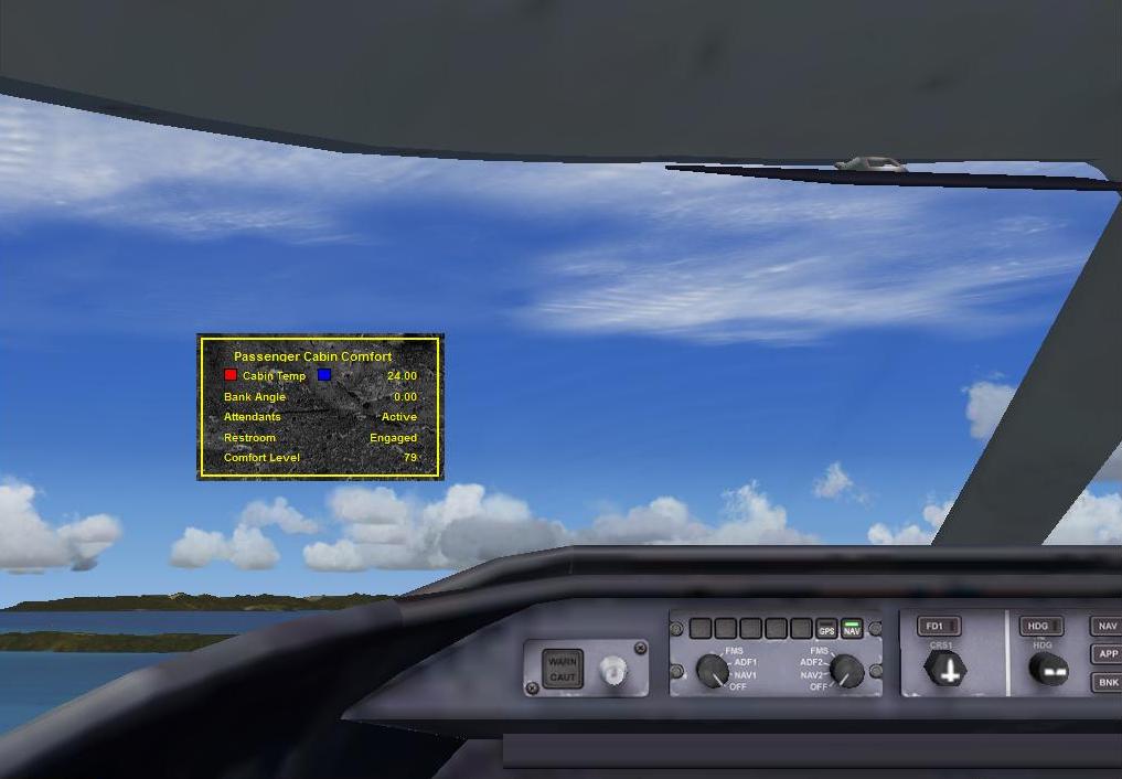 |
The sample is a very simple gauge, evaluating how comfortable the passengers are based on the cabin temperature, bank angle, activity of the attendants, and state of the restroom. The cabin temperature is controlled from the gauge, click the red rectangle to increase the temperature, and the blue rectangle to decrease it.
The steps in building a gauge system combining XML and C++ can be done in a different order than described here, but the following steps provide a logical process to go about creating such a gauge. One of the advantages of combining XML and C++ is that the gauge graphics can be created with the assistance of the ACE tool, described in the Creating XML Gauges document, which considerably speeds up the trial and error process.
Use the ACE tool to help create a great looking gauge. The only parts of the XML gauge that communicate with the C++ component are the evaluated strings. A name for the C++ component needs to be decided upon (the word "CABIN" in the sample), and also names for the variables that are going to be communicated (either read or write). For the Cabin Comfort sample, the evaluated strings are the following:
String |
Description |
| <GaugeString>%((C:CABIN:CabinTemperature))%!2.2f!</GaugeString> | Displays the cabin temperature as a float, with two decimal places. Note in particular the double brackets surrounding the custom variable. The cabin temperature is set from the gauge - see the two mouse click scripts below. |
| <GaugeString>%((C:CABIN:BankAngle))%!2.2f!</GaugeString> | Displays the bank angle, again to two decimal places. |
| <GaugeString>%((C:CABIN:FlightAttendants))%!s!</GaugeString> | Displays a string indicating the current activity of the flight attendants. |
| <GaugeString>%((C:CABIN:Restroom))%!s!</GaugeString> | Displays the state of the restroom. |
| <GaugeString>%((C:CABIN:PassengerComfort))%!3.0f!</GaugeString> | Displays the Passenger Comfort setting, with no decimal places. |
| <Script>(C:CABIN:CabinTemperature) 50 < if{ (C:CABIN:CabinTemperature) 1 + (>C:CABIN:CabinTemperature) }</Script> | If the cabin temperature is less than 50 degrees, 1 is added to the current temperature and the result written back to the cabin temperature variable. |
| <Script>(C:CABIN:CabinTemperature) 0 > if{ (C:CABIN:CabinTemperature) 1 - (>C:CABIN:CabinTemperature) }</Script> | If the cabin temperature is greater than 0 degrees, 1 is subtracted from the current temperature and the result written back to the cabin temperature variable. |
Test and refine the XML as much as possible before coding the C++ component.
In the code snippets shown below, from the Cabin_Comfort.cpp file, note the definition of the callback name "CABIN", and the names of all the variables, exactly match those in the XML code from Step 1.
struct PROPERTY_TABLE |
Examine the CABINGaugeCallback class, which inherits the IGaugeCCallback class defined in gauges.h. The simplest way of initializing any variables is to do it in the creation function of this class.
CABINGaugeCallback::CABINGaugeCallback(UINT32 containerId) |
Notice though that the property table defined in Step 2 is initialized in the creation function for CABINPanelCallback. If a string is the units of a variable, set the value to UNITS_STRING in the property table, otherwise set it to UNITS_UNKNOWN. The following code then finds all the unknown units and finds the enumeration value for the units. This is necessary as the actual enumeration values for any units are not exposed, and may change in future versions. By calling get_units_enum this initialization code is made more robust.
CABINPanelCallback::CABINPanelCallback() |
Notice there are two methods for both getting and setting property table values. One method handles strings, the other numerical values. The CabinTemperature property is the only one that can be set from the gauge controls in the Cabin Comfort sample, and the code to do this follows:
bool CABINGaugeCallback::SetPropertyValue (SINT32 id, FLOAT64 value) |
The CABINGaugeCallback::Update() method is called optimally on a cycle of 18Hz (18 times per second), however it should be pointed out that the actual frequency can be somewhat lower than this, as optimizations are made to maintain frame rates. This function is the right place to put code to change variables that is not dependant on a get or set call. For some gauges this method may well not contain any code at all.
Two very important methods are module_init and module_deinit. The code for these is shown below. These methods are called when the dll is created and removed respectively. Notice in particular the Panels pointer, shown in bold, that is set to NULL. This value is set by the DLL launch code.
|
A key component of the gauge project is the Cabin_Comfort_Def.def definition file. This contains the following:
| LIBRARY "Cabin_Comfort" EXPORTS module_init module_deinit Panels DATA |
This small piece is vital, as it exports the initialization and termination method names in an undecorated format, and provides the pointer to the Panels data that is absolutely required to be set when the dll is loaded.
The C++ project should compile into a dll. Follow the steps for running the Cabin Comfort sample to test your own gauge, including adding a <Launch.Addon> section for it to the DLL.XML file. Make sure to place all the different components in the correct folders.