
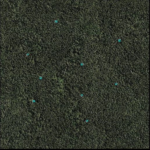
Autogen is the Flight Simulator X process that generates the default scenery objects. The simulated world is divided into a grid, each square roughly 1.2 by 1.2 kilometers, and each grid square will have a texture applied to it based on its land classification (see the Terrain and Scenery documentation for details). The textures for land classification can have an associated annotation file, which contains footprints of buildings and vegetation. If a specific building model is required, then a library object can be placed on the texture. However, for the majority of buildings this would result in a very repetitive landscape. For this reason, only the footprint, range of heights, and building textures are contained in the annotation file. The autogen process will select or construct an appropriate building model at run time, therefore creating much more varied and realistic landscapes.
This document explains how to annotate textures with buildings and vegetation, and modify or replace default scenery textures.
Textures are annotated using the annotator.exe tool.
The Control Strip is a floating window that may be positioned anywhere on the desktop. You can use the Control Strip to select the annotation editing mode. The mode selection determines the action of your mouse. Using these modes, you can create building and vegetation footprints, place library objects and row houses, and also pan textures and select and manipulate objects.
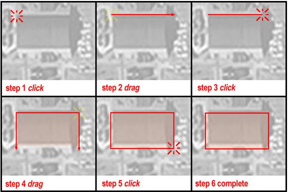
Choose one of these modes to create building and vegetation footprints, specific to the region, on the ground texture. See Creating Building and Vegetation Footprints.
Choose this mode to pan the texture within the workspace. Click and drag anywhere in the workspace to move the visible portion of the image. Alternatively, you can pan the texture in any mode by using the middle mouse button (or mouse wheel button) to click and drag.
Choose this mode to zoom in and out on the texture. To magnify a section of a texture, click the left mouse button anywhere in the workspace. To zoom out, click the right mouse button. You can also zoom in or out in any mode by rolling the mouse wheel up and down.
Choose this mode to select building and object footprints and vegetation areas. To select any footprint or vegetation area, click it. To select multiple objects, hold down the Ctrl key and then click each object that you want to select, or click and drag a selection area. You can then move, cut, copy, paste, or delete the selected objects.
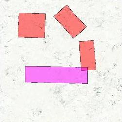
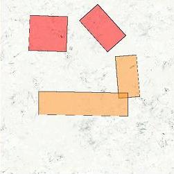
Choose this mode for a very quick method of pasting selected building footprints, vegetation areas, and library objects onto the texture. Select one of more objects as described above for Select mode, then click Paste (A). Now on the texture, click the left mouse button to paste the selection as many times as desired.
 |
 |
To set properties that control the runtime generation of buildings, use the options in the Annotation Properties dialog box (in the File menu of the Annotation tool, click Properties).
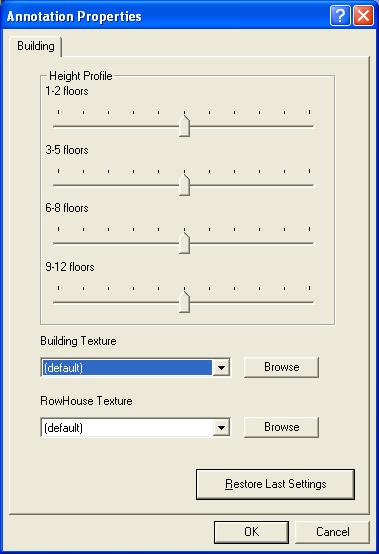
Use the height profile sliders to set the building height profile for the current texture. The height of each building is generated at runtime, but these sliders control the height profile. The further to the right each slider is, the more buildings of that type are generated.
For example, in a typical suburban ground texture, most of the buildings have 1 or 2 floors, a few buildings have 3 to 8 floors, and no buildings have 9 or more floors. To create this building height profile:
Similarly, in a more urban or industrial ground texture, move the sliders that control the taller buildings to the right, and move the sliders that control the shorter buildings to the left. Fundamentally, the slider values represent the relative probability that a particular height will be selected for each individual building footprint. However, to prevent the creation of oddly sized buildings, there are two exceptions: if a building footprint is either small (less than 625 square meters) or very large (greater than 1600 square meters), the height will be forced to one or two stories at runtime.
Use the Building Texture list to select the bitmap that will be used to texture the buildings. You can modify the default texture or create new autogen building textures. For more information, see Autogen Texture Sheets.
Use the RowHouse Texture list to select the bitmap that will be used to texture any row houses. You can modify the default texture or create new autogen row house textures. For more information, see Autogen Texture Sheets.
If you want to reset the slider values for the texture to their original settings, click this button.
Autogen uses a number of texture sheets to define the appearance of buildings and vegetation. These texture sheets take advantage of as much texture space as possible to deliver the maximum amount of visual difference in how autogen objects appear, while remaining a minimal burden on texture memory resources. Autogen uses four classes of textures: building, row houses, library and vegetation. You can edit these textures to customize the appearance of the default scenery. These four texture classes have different layouts, which are described in the following sections.
In the FSX/texture folder there are a number of texture sheets for autogen buildings that represent day and night variations of buildings in different regions of the world. Each texture map is constructed to follow a consistent layout, regardless of the time of day or location. The following diagrams illustrates the basic layout of a building texture, and the layout in pixels.
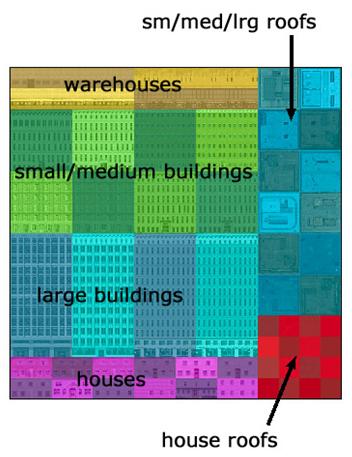 |
Textures are mapped to buildings that meet certain constraints. For example, only buildings that fit a certain profile (building footprint, building height) will be textured with one of the four warehouse texture variations (color-coded yellow above). Autogen building texture sheets are 512 x 512 pixels in total size. However, individual texture areas that describe the sides of a building are formed by smaller subunits called cells. Cells are 16 x 16 pixels in size. On a building side texture, one cell is equal to approximately one story of building height and an equal measurement in the building’s width. Roof textures are composed of single cells. Depending on the vertical height, length, or width of a particular building, autogen clips to the nearest cell.
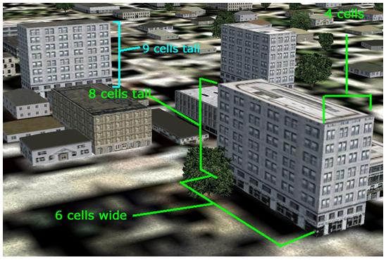
For example, in the diagram below, autogen uses the entire 6 cells of available width on one side, 4 out of 6 cells on another side, and 8 out of 12 cells of height. In the building in the background, 9 out of 12 cells of height are used.
 |
 |
One significant difference between Autogen for Flight Simulator 2004 and Flight Simulator X is the handling of roof textures. The layout of the textures has not changed, but the process for handling house roofs has. The office buildings and warehouses still use the system described above. However, for house roof textures there is now a RoofDescriptions.xml file that includes regional information and variations on house roofs. House roof texture files that are referenced from the RoofDescriptions.xml file can have a varied format (the texture co-ordinates are in the xml file).
In the FSX/texture folder there are a number of texture sheets for Row House buildings. The following diagram illustrates the basic layout of the textures.
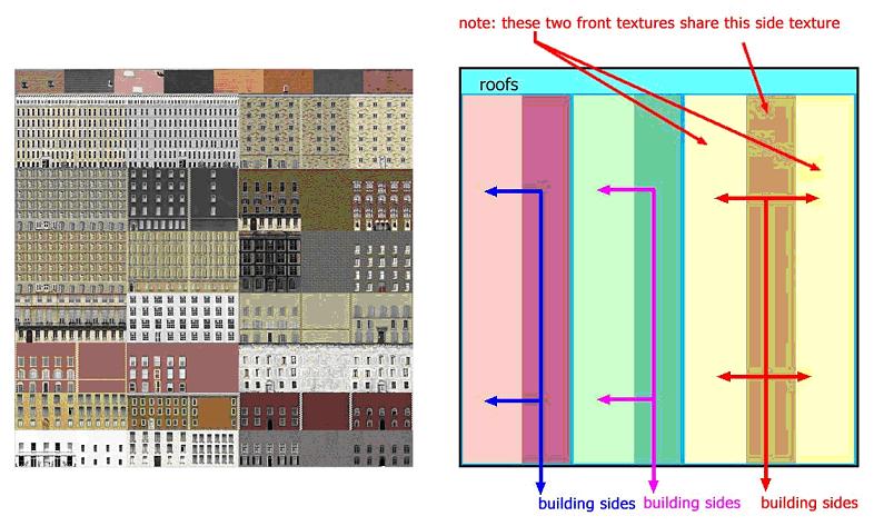 |
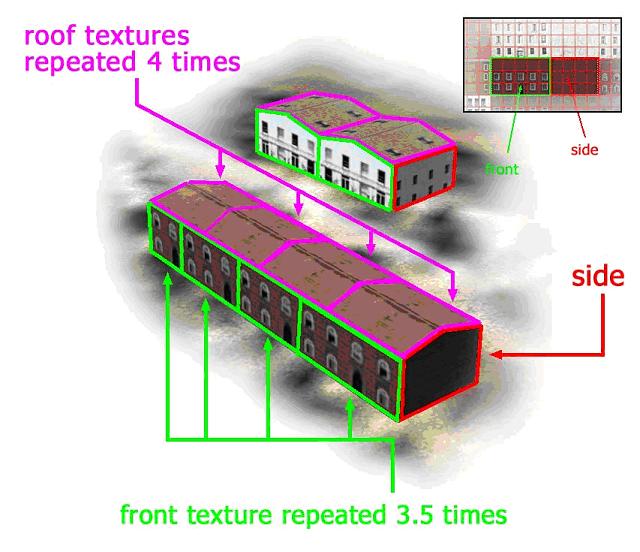
Textures are mapped to buildings that meet certain height constraints. Unlike the default autogen buildings that use a tiling texture that wraps around all sides of a building, all Row House buildings use two textures. The first texture (designated as “front” in the figure above) is used to texture the longest sides of the building, and the second texture (designated as “side”) is used to texture the shortest sides. An additional difference between Row House textures and default buildings lies in how the roofs are textured in each. Default buildings select from a variety of roof textures based on building type and size. Row House buildings select one roof texture from a pool of equal sized textures regardless of building size. Row House building texture sheets are 512 x 512 pixels in total size.
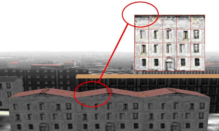
The next illustration demonstrates how Row House textures are tiled across the face of a given side or top of a building. On the Row House texture sheet, there is a 3 x 4 cell area of unique texture available for the front of a building that fits this height profile, and a 3 x 4 cell area for the side. In the nearest building below, autogen uses an entire 3 x 4 cell area of available width and height for the front of the building, and tiles that group of cells 3.5 times across the length of the building. The side of the building also uses a different 3 x 4 cell area, but only for one instance. The roof of this building uses one roof cell tiled 4 times. Depending on the length or width of a particular building, autogen clips to the nearest cell. In the building in the background, a 3 x 4 cell area is tiled twice across the long face, once across the side, and twice along the top. Because Row Houses have roofs that are pitched across either the long front or the short side, there is a small amount of texture clipping in the cell area adjoining the roof (see the second illustration below).
 |
 |
The Polyline building is a new type of autogen object introduced in Flight Simulator X, and is most often used to render courtyard-type buildings. These objects are extruded from a two-dimensional profile generated by an art tool such as 3dsMax. There are nine basic profiles from which all of the polygon autogen buildings are created. The profiles simulate three different roof types and each type comes in three different heights – three stories, four stories and five stories. Each profile also includes a one story basement section. There are two or three textures assigned to each courtyard building – either one or two roof textures, and a side texture. Polyline buildings do not get specular or normal maps but do get a night map.
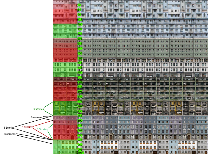
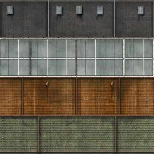
The side texture is a tiling 1024x1024 texture that incorporates 32 floors with each floor occupying 32 pixels vertically and 1024 pixels horizontally. The floors are arranged vertically in such a way that the specific sections of the texture can be mapped to 3-story, 4-story or 5-story courtyard buildings (shown in red in the image below). In other sections the only mapping allowed is to a 3-story building (shown in green). In all cases, one additional story is mapped to the basement of the building. There are two variations of each side texture for each of the 26 world regions (refer to the Terrain and Scenery document for a description of the regions), for a total of 52 variations. Roof textures are not regionalized. The side textures should be saved as a DXT1 (without alpha) DDS. These textures have a BLD_ prefix followed by a regional designator and a version number (for example BLD_Europe_North_1.dds).
 |
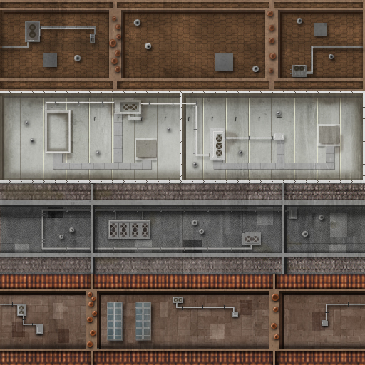
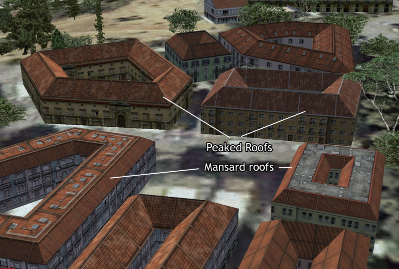
Polyline roof textures come in two flavors: sloping roof textures and flat roof textures. The sloping roof textures are intended to map to the angled sides of peaked and mansard style roofs. The flat roof textures are intended to map to the flat top sections of mansard style roofs and also to flat roofed buildings. Each texture is a 512x512 DXT1 without alpha in DDS format, and is divided into four individual roof textures occupying 128 pixels vertically and 512 pixels horizontally. These textures tile horizontally but not vertically.
The texture files have a prefix of BLD_roof_ and a “Top” or “Side” indicator in the name (for example: BLD_Roof_Top_L01.dds, BLD_roof_side_K02.dds). There are six top variations and six side variations as well as night map versions for each. Buildings with mansard roofs use two roof textures (one side and one top); all others use one roof texture, either one top or one side texture.
Example top roof texture |
Example side roof texture |
 |
 |
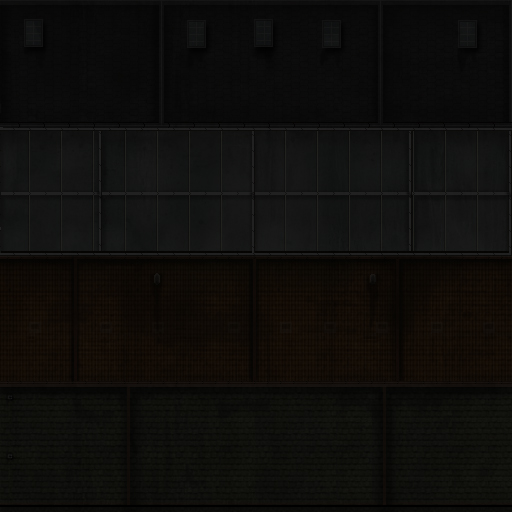
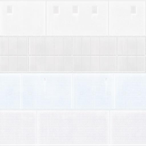
Example of a night map for the top roof texture shown above |
Inverting the night map image reveals a bit more detail |
 |
 |
Example of polyline buildings |
 |
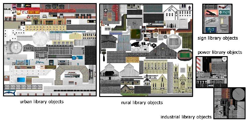
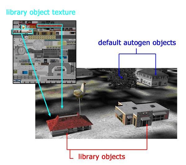
To create a richer visual environment, autogen can display more complex 3D shapes selected from a library of generic types. Because these objects are more complex, each 3D object has dedicated texture coordinates unique to that object. Some objects may share texture space with other objects (for example, two different motel models may use the same texture of a swimming pool, but the location, shape, and size of the pool can differ in each motel), but even then the texture coordinates are different from object to object. It is possible to edit the textures themselves, but not to change the texture coordinates used by the models in question. The illustration below shows some example texture sheets used for autogen’s library objects, and the second illustration shows an example of more complex shaped objects.
 |
 |
To create custom building textures for Autogen, go through the following procedure:
The Autogen Configuration Editor tool can be used to edit many of the files that define the autogen procedure. In the Flight Simulator X/Autogen folder there is the default.xml file, and the other files listed here are in the Environment Kit/ Autogen SDK/Autogen source xml folder (it these files are edited, then place the new files in the Flight Simulator X/Autogen folder to be read by Flight Simulator).
File |
Description |
Editable with AutogenConfigEditor |
| AutogenDescriptions.xml | Describes the vegetation groupings and regionalizations. Vegetation models (trees, shrubs etc.) are referenced from within the file. | Yes. Add, remove or modify vegetation groupings and weights, and add or remove individual vegetation model references. See Vegetation Groupings. Care should be taken to make sure all the seasonal variations are added for new models.
Note the MaxScale and MinScale parameters are not implemented in this version of Flight Simulator X. |
AutogenDescriptions_mid.xml AutogenDescriptions_min.xml |
These are variations of the AutogenDescriptions file that reduce the rendering complexity of the vegetation. Which file is used depends on the AutogenDescriptionsFilename setting in the [Terrain] section of the FSX.cfg file. | Yes. If new groupings or models are added, then they should be referenced in all three descriptions files, otherwise gaps could appear in the scenery during certain seasons, or might occur depending on which descriptions file the user has specified in the configuration file. |
| default.xml | Defines the library objects associated with each region and class of automatically generated scenery. | No. See the section Editing the Default.xml file. |
| Extrusions.xml | Extrusions are vertical objects than are not of a fixed size so cannot be defined by individual models, such as fences and extrusion bridges. | No. To add extrusions as scenery, use the BGL Compiler. |
| Materials.xml | This file contains references to materials used by the other xml files. | Yes. Add or modify materials. |
| RoofDescriptions.xml | Describes the default roofs to use for the various buildings. | Yes. Similar to vegetation. Add, remove or modify groupings and weights, and add or remove individual model references. |
| TerrainAutogenClassDescriptions.xml | Describes the default land classifications. | No. It is not recommended that this file is changed. |
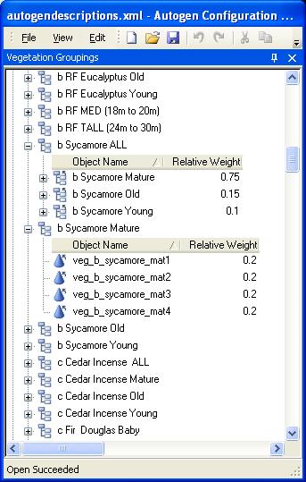
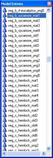
With the AutogenDescriptions.xml file open in the Autogen Configuration Editor, ensure the Vegetation Groupings and Model Entries windows are open. In the example below the grouping b Sycamore ALL refers to three other groupings (Mature, Old and Young). The relative weights are totaled (they need not total to any specific number) and the number of times a sub-grouping is chosen is calculated by dividing the relative weight by the total weight. For example, Sycamore Mature will be chosen for 75% of the vegetation areas referencing this grouping, Sycamore Old 15% of the areas, and Sycamore Young 10% of the areas. The Sycamore Mature grouping contains references to four models, each with an equal weight, so each model will be chosen for 25% of the vegetation areas.
A grouping can contain references to both other groupings and individual models. In all cases the relative weights determine how often a model, or group of models, is to be used. When creating vegetation areas using the Annotator tool, select any level of vegetation from the high level groupings to the particular model entries, and an appropriate selection of that vegetation will be rendered at run-time.
 |
 |
Polyline vegetation is rasterized into a sampling bitmap. The granularity of the rasterization is determined by the following setting in the fsx.cfg file:
[TERRAIN]

IMAGE_PIXELS_FOR_AUTOGEN_POLYGONS=16
The value of this setting is set at the minimum, 16, and can be any value up to 2048. The higher the number the more accurately a curved polygon will be rasterized. The value 16 indicates a rasterization of approximately 80 meters down to approximately 0.5 meter accuracy for the 2048 setting. There is a performance penalty with the time it takes to rasterize a region, and the memory required for the resulting sampling bitmap.
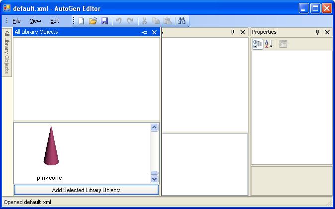
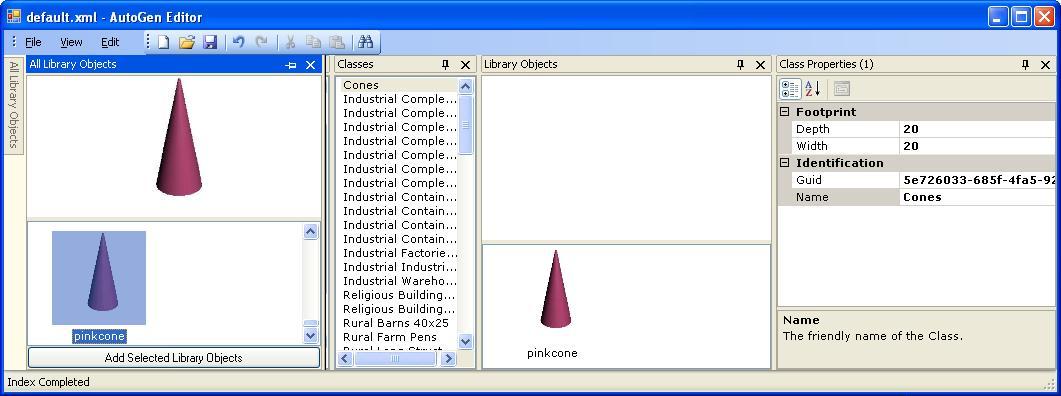
The default.xml file defines the library objects associated with each region and class of automatically generated scenery. It can be edited with the AutogenEditor tool (not to be confused with the AutogenConfigEditor tool). The following tutorial goes through the entire process of adding new models and classes to the default.xml file, and then testing those new models in Flight Simulator itself. It is quite an involved process, involving a minimum of four tools.
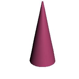
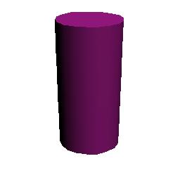
In this tutorial a new class, Cones, will be added to Autogen, with a couple of suitable models. Models within a class appear at random, so the more models that are added to a class, the more varied the landscape. However, for the purpose of this tutorial we will create just two models, and these will be very simple and somewhat unsightly, in order to focus the tutorial on the Autogen tools, and not on the creation of models (see the New Aircraft Procedures and the Texturing Aircraft Models document for information on how to create good 3D art).
3ds max 8 is used in the tutorial to create the models, the screen shots and procedures will vary slightly for other art tools. Make sure that you are using the latest version of the SDK tools.
PinkCone.jpg |
PurpleCylinder.jpg |
 |
 |
This step only applies to users of 3ds max. The gmax exporter writes directly to an .MDL file, so users of this tool should copy the .MDL files over to the Environment Kit/BGL Compiler SDK folder, and then go to Step 3.
<?xml version="1.0" encoding="ISO-8859-1" ?>
<ModelData sourceFile="pinkcone.MDL" />
</FSData> |
| <setting name="ObjectsPath" serializeAs="String"> <value>%ProgramFiles%\Microsoft Games\Microsoft Flight Simulator X\Scenery\Global\Scenery\autogen.bgl;Cones.bgl</value> </setting> |
 |
 |
| - <CLASS> <NAME>Cones</NAME> <GUID>88a4b4ff475ce44c614381a2d013b18f</GUID> <WIDTH>20</WIDTH> <DEPTH>20</DEPTH> - <LIBRARYOBJECT> <NAME>PinkCone</NAME> <GUID>95be2ae047e5793c67fd16a788fa9a10</GUID> </LIBRARYOBJECT> - <LIBRARYOBJECT> <NAME>PurpleCylinder</NAME> <GUID>bde51d6d4b6ed09240c85d8e4fdc6592</GUID> </LIBRARYOBJECT> </CLASS> |
 |
It is possible to edit the default.xml file by hand, using a text editor, though this is no longer the recommended method. If this method is used, then ensure that a new class is added to all regions, and note that the GUID format is an old format that the new Guid creation tools do not provide. The table below provides a link to a code snippet which can be used to reformat guids.
The following table shows a section of the default.xml file.
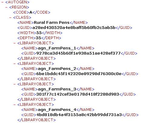 |
The following table describes the xml tags used in the file.
Tags |
Description |
| <AUTOGEN> | Wrapper tag for entire file. |
| <REGION> <CODE> | This corresponds to the region code used by the simulation. For a list of the region codes and the areas they represent, see the Regions section of the Terrain and Scenery document. |
| <CLASS> <NAME> <GUID> <WIDTH> <DEPTH> | The name is the class name that will appear in the annotator.exe tool. The GUID is used to uniquely identify the class, create a new GUID if you intend to create a new class. Note that the GUIDs stored in this file are in an older format than generated by the GUID creation tools referenced by this SDK documentation. Refer to the GUID Formats section of the Compiling BGL document for a code snippet that will convert from one GUID format to the other.
WIDTH and DEPTH specify the size of the footprint, in meters. This size is used by the Annotator.exe tool, not by Flight Simulator. Library objects are of a fixed size. |
| <LIBRARYOBJECT> <NAME> <GUID> | The name of the library object, and its unique GUID. |
It is possible to add new library objects, and new classes, to this file. It does not make sense to add new regions.
Autogen objects can be excluded from certain areas by using the Shp2Vec tool described in the Terrain and Scenery documentation. There is a slightly different call for excluding scenery objects, such as buildings and trees, than for vector data, such as streams and utility lines. This enables exclusion of autogen features in a fairly small area. Autogen objects are also dependent on the land classification code, which can be changed using the Resample tool, also described in the Terrain and Scenery documentation.
There are a number of tools that can be used to validate various autogen files. These tools are all command-line driven, and each has its own config file ( a file with the same name as the tool, but with .config appended to it) describing its default behavior. There are four levels of text output: verbose, information, warnings and errors. The output level is set in the config file. The tools are described in the following table.
Tool |
Description |
| AC2Scan | Validates the default.xml file (found in the Flight Simulator X/Autogen folder), checking for consistency with the regions and classes within the file, and that the GUIDs reference models that exist. |
| AC3Scan | Validates the AutogenDescriptions, Extrusions, Materials, RoofDescriptions and TerrainAutogenClassDescriptions files (either XML or SPB versions), primarily checking for the existence of models and textures. |
| AGNScan | Validates .AGN (autogen annotation files) primarily checking that the GUIDs referred to exist in the appropriate configuration files. |
| ContentScan | This tool combines the three autogen validation tools, along with the BGLScan and MDLScan tools. This tool does not take any inputs, all the settings it uses are in the ContentScan.exe.config file. |
The AutogenDescriptions, Extrusions, Materials, RoofDescriptions and TerrainAutogenClassDescriptions files can either be in XML or SPB (Sim-Prop Binary) format. See the section Creating an SPB File in the Creating XML Gauges document for details on how to use the simpropcompiler tool.