
The BGL Compiler is primarily used to compile scenery and airport data into files that Flight Simulator X can read. It is also used for creating Rewards files for the mission system, and adjusting time zone information.
Scenery created for Flight Simulator 2004 is compatible with Flight Simulator X. Scenery should no longer be created with BGL op-codes or the BGLC compiler from previous versions of Flight Simulator. The older BGL op-codes are supported for backward compatibility, however, we cannot guarantee their support in future releases.
GUIDs are now entered in the following format (complete with curly brackets and dashes): {93802d8b-ba4f-45eb-a272-9f029a0feeb3}. The example shows a GUID for a water tower. In earlier versions of Flight Simulator, GUIDs were entered as a 32 character hex string.
See the SDK Overview section on Generating GUIDs to access a tool that will generate new style GUIDs. If for any reason GUIDs need to be converted from the old format to the new, or vice versa, use the following piece of C# code. If an old format GUID is provided as the parameter, a new format GUID will be returned, and if a new format GUID is provided as the parameter, an old format GUID will be returned.
GUID conversion code |
public static Guid ChangeGuidFormat (Guid guid) |
If you are running an operating system earlier than Windows XP you will need to ensure that MSXML4 is installed on any machines that will run BGLComp. You can find MSXML4 on the Microsoft web site: http://www.microsoft.com.
If you are running the Windows Vista operating system you will need to be working as an administrator for BGLComp to work correctly.
The BGL compiler is invoked with the command:
bglcomp.exe <filename>
To make batch file processing easier, the compiler will accept wildcards to process multiple files per invocation. Invoking the compiler without any parameters will print version and usage information for the compiler. Along with the compiler is the file BGLComp.xsd, this file must be located in the same directory as BGLComp.exe for the compiler to function properly.
The scenery format is XML-based and follows a strict file structure with regards to element hierarchies, case sensitivity, and the contents of elements (potentially including white space). XML is a text-based file format consisting of elements and attributes. The XML specification also allows for comments, to allow scenery files to be annotated. At this time elements, attributes, and values are all case-sensitive. The XML convention used is as follows:
See the Microsoft website (www.microsoft.com) for more information about XML.
The following is a sample of the XML file structure used for scenery files. Note the use of ‘<!--‘ and ‘-->’ to start and end comments.
<?xml version="1.0"  encoding="ISO-8859-1"?>

  <FSData

       version="9.0"

       xmlns:xsi='http://www.w3.org/2001/XMLSchema-instance'

       xsi:noNamespaceSchemaLocation="bglcomp.xsd"  >

  <!-- Facility and scenery data goes here -->

  </FSData>
For more information on how to create new terrain refer to the Terrain and Scenery document. Both facility and scenery information may be contained in a single .XML source file and this practice is encouraged.
Spatial sorting is important to reduce file size and increase engine efficiency. It is up to the scenery creator to break the source into geographically related areas to optimize how the scenery is loaded into memory. When deciding on boundaries it is beneficial to avoid overlapping file bounds between files.
The XML compiler has been designed to be very strict in an effort to avoid ambiguity. As a result, the strings used for XML elements and attributes are treated as case-sensitive. The compiler will report such errors at compile time.
Some scenery elements are not allowed to contain other sub-elements. The form of the XML is used to distinguish between these types of elements.
Elements allowed to have sub-elements take this form:
<Element attribute="value">

        <SubElement>

              <!--  Sub element data -->

        </SubElement>

  </Element>
Elements not allowed to have sub-elements take this form:
<Element attribute="value" />
If an element that is not allowed to have sub elements isn’t closed with ‘/>’ or contains any data (including white space) before the closing element tag, the following error will result:
ERROR: 19, 66, Text is not allowed in this context according to DTD/Schema.
The XML standard is very strict in this regard and it is essential to have the proper closing on an element. If the element is allowed to contain data, the element is closed with a declaration of the element prefixed with a ‘/’ character (i.e., </ClosingElement>). If the element is not allowed to contain sub-elements the declaration is closed with ‘/>’. This is an important distinction that will be checked during XML validation. The appropriate structure of these elements will be shown in their descriptions.
When errors are reported from the compiler, they generally start with the line number and character position on the line where the error occurred. This format is mainly used when an XML format error occurs and sometimes when a data content error occurs. All of the .XML content is validated against an .XSD to ensure proper file structure before processing in the compiler. As a result, ordering of sub-elements is verified. If elements are found to be out of order, the following error will result:
ERROR: 5, 48, Element  content is invalid according to the DTD/Schema.

  Expecting: Effect,  GenericBuilding, LibraryObject, Trigger, Windsock, AttachedObject.
This is .XSD validation code reporting what it expects to see next. Check the XML at the line noted and see if there is an element that might be out of order, or whether multiple instances of a sub-element are allowed.
Some of the entries in the FSX.cfg configuration file reference scenery, terrain and graphics issues. The FSX.cfg file is found in the Documents and Settings\<username>\Application Data\Microsoft\FSX folder.
Entry |
Description |
| MissingLibraryAlert=1 |
Receive error messages when library objects are referenced but not found, or when library objects that have bounds are referenced outside of those bounds (for example, the Seattle Space Needle model can only be referrenced in the Seattle locality). |
ShowMissingTextureAlert=1 |
Receive warnings when one or more scenery object or aircraft model textures are missing. Note that setting this will not trigger an error message for missing terrain textures. |
Entry |
Description |
| Day_Threshold | A value between 0 (total darkness) to 65535 (full day sun at noon in summer) that represents the amount of ambient light to apply to textures at the end of the day/night threshold. The default value is 32768 (50 percent of full brightness). The smaller the difference between Day_Threshold and Night_Threshold, the quicker twilight and sunrise will be. |
| Night_Threshold | The default value is 4096 (6.25 percent of full brightness). |
Scenery objects are placed inside of the <FSData> elements. The following XML shows the XML file structure used for scenery objects and will put an oil drilling rig next to the runway at SeaTac airport.
<?xml  version="1.0"?>

  <FSData

       version="9.0"

       xmlns:xsi='http://www.w3.org/2001/XMLSchema-instance'

       xsi:noNamespaceSchemaLocation="bglcomp.xsd"  >


  <SceneryObject

        lat="N47 25.89"

        lon="W122 18.42"

        alt="0"

        altitudeIsAgl="TRUE"

        pitch="0"

        bank="0"

        heading="0"

        imageComplexity="NORMAL">


        <LibraryObject

              name="{93802d8b-ba4f-45eb-a272-9f029a0feeb3}"

              scale="1.0"/>

  </SceneryObject>

  </FSData>
All scenery objects are contained within a SceneryObject element. The SceneryObject element has several required attributes that define the placement of the object in the world. For this sample, the SceneryObject contains a LibraryObject that represents a water tower.
The following sections list the elements and associated attributes that can be used to create scenery. Some scenery XML elements are used to contain other elements, while others are not. This distinction is shown by the form of the data.
This element is used to designate an object’s placement in the world. It can be used to specify the lat, lon, alt position of the object, and the pitch, bank and heading to be applied. This element is allowed to contain Bias, Beacon, Effect, GenericBuilding, LibraryObject, Trigger, Windsock, AttachedObject data and should not be terminated with ‘/>’. The AttachedObject entry must be the last.
<SceneryObject

      lat=" 32.69398294"

      lon=" -16.77601783"

      alt="0"

      altitudeIsAgl="TRUE"

      pitch="0"

      bank="0"

      heading="0"

      imageComplexity="NORMAL">


      <!-- Scenery object data elements -->

      <BiasXYZ

          biasX="0"

          biasY="0"

          biasZ="0"/>  <!-- Optional -->


      <LibraryObject

          name="GUID"

          scale="1.0"/>


      <AttachedObject ......>       <!-- Optional -->

      </AttachedObject>

</SceneryObject>
Attribute |
Description |
Acceptable Values |
| instanceId | Optional GUID that identifies this SceneryObject entry. | GUID in the format:
|
| lat | Latitude of object | -90 to +90 degrees Format can be decimal or degrees-minutes-seconds |
| lon | Longitude of object | -180 to +180 degrees Format can be decimal or degrees-minutes-seconds |
| alt | Altitude of object | Any floating point value. May be suffixed by M or F to designate meters or feet. Default is meters. |
| altitudeIsAgl | Boolean indicating whether altitude is AGL or MSL | TRUE = alt is AGL FALSE = alt is MSL |
| pitch | Pitch applied to object | 0.0 to 360.0 floating point value |
| bank | Bank applied to object | 0.0 to 360.0 floating point value |
| heading | Heading applied to object | 0.0 to 360.0 floating point value |
| imageComplexity | Minimum image complexity setting for the objects to appear. For example, objects set at NORMAL will appear if the setting is DENSE, but not appear if the setting is SPARSE. | VERY_SPARSE SPARSE NORMAL DENSE VERY_DENSE |
The following elements can be added to a SceneryObject, but contain no additional attributes or elements, so are entered into the XML, for example, as <NoAutogenSuppresion/>.
Element |
Description |
| NoAutogenSuppression | Do not suppress Autogen created objects that might be on the same terrain as the scenery object. |
| NoCrash | Aircraft do not crash if they hit this object. |
| NoFog | Fog does not affect the object at render time (useful for the virtual EFIS objects that draw in the sky). |
| NoShadow | Objects do not create a shadow. |
| NoZWrite | Allows an object to draw into the scene but not write to the ZBuffer. Note that there is no control over the draw order. |
| NoZTest | Allows an object to draw into the scene without testing against the ZBuffer. This causes objects to draw on top of others. Note that there is no control over the draw order. |
This element is used to add an X, Y, Z bias in meters to the placement of an object. The acceptable range of values is unbounded, but it is recommended that biases only be applied for small distances. If this element is used inside of a SceneryObject it must come before any instances of AttachedObject, Effect, GenericBuilding, LibraryObject, Trigger, or Windsock. This bias is not affected by pitch, bank, or headings applied to the base scenery object. This element is not allowed to contain other data and must be terminated with ‘/>’.
<BiasXYZ

        biasX="0"

        biasY="0"

        biasZ="0"/>
Attribute |
Description |
Acceptable Values |
| biasX | Bias along the longitudinal axis in meters | Floating point value |
| biasY | Altitude bias in meters | Floating point value |
| biasZ | Bias along the latitudinal axis in meters | Floating point value |
This element is used to add a scenery effect to the scene. See Creating Special Effects for more information about creating and using scenery effects. This element is not allowed to contain other data and must be terminated with ‘/>’.
<Effect

        effectName=" FW_Controller"

        effectParams="  MOY=01,01;DOM=01,01;HOD=00,00;MOH=00,20;"/>
Attribute |
Description |
Acceptable Values |
| effectName | Name of the effect | String (up to 80 characters) |
| effectParams (optional) | Parameters for the effect. See the Special Effects documentation for more information. | String of parameter settings, may be empty. |
This element is used to add a generic building to the scene. The building type and parameters are set as sub-elements. This element is allowed to contain RectangularBuilding, PyramidalBuilding, and MultiSidedBuilding data and should not be terminated with ‘/>’.
<GenericBuilding

        scale="1.0"

        bottomTexture="68"

        roofTexture="25"

        topTexture="68"

        windowTexture="41">

        <!-- building data -->

  </GenericBuilding>
Attribute |
Description |
Acceptable Values |
| scale | Scale value for building that represents the number of meters per unit. Set to 1.0 for the building to be modeled in meters. | Floating point value. |
| bottomTexture | ID of texture to use on bottom layer. | Integer. See Generic Wall Textures. |
| roofTexture | ID of texture to use on roof | Integer. See Generic Roof Textures. |
| topTexture | ID of texture to use on top layer | Integer. See Generic Wall Textures. |
| windowTexture | ID of texture to use on window layer | Integer. See Generic Window Textures. |
The textures for walls for generic buildings are divided into two. The lower half provides textures for one design of building, and the upper half for another. The textures for roofs and windows are not divided into two, the whole texture is used. In the examples in this document the following textures are used:
Texture number |
Texture |
Notes |
| 68/69 | 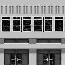 |
This texture is for skyscraper buildings, and is divided into four regions. The lowest shows the bottom layer (street level) of a building. Just above it is the top layer that is rendered above the windows. The third layer is an alternative lower level (street level again), and above that another top level. The texture number 68 references the bottom layer, and number 69 the top layer. This texture is 128x128 pixels, |
| 68/69 | 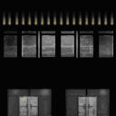 |
This texture is used for the building walls at night time. |
| 25 | 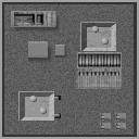 |
A roof texture, clearly designed as the flat roof top of a skyscraper, although we use it for many of the building examples here. This texture is used for both day and night time. The texture is 128x128 pixels. |
| 41 |  |
This texture is used for skyscraper windows. It is 64x64 pixels. |
| 41 |  |
This is the window texture used at night time. |
This element is used inside of a GenericBuilding element and is used to describe a rectangular building. Rectangular buildings have many possible attributes and the availability of attributes is determined by one of four roof types: (FLAT, PEAKED, RIDGE, SLANT).
This element is not allowed to contain other data and must be terminated with ‘/>’. The following is a list of the valid roof types and their attributes:
<RectangularBuilding

        roofType="FLAT"

        sizeX="44"

        sizeZ="44"

        sizeBottomY="5"

        textureIndexBottomX="512"

        textureIndexBottomZ="512"

        sizeWindowY="250"

        textureIndexWindowX="1024"

        textureIndexWindowY="2048"

        textureIndexWindowZ="1024"

        sizeTopY="5"

        textureIndexTopX="512"

        textureIndexTopZ="512"

        textureIndexRoofX="256"

      textureIndexRoofZ="256"/>
Attribute |
Description |
Acceptable Values |
| sizeX | Size of base along longitudinal (east-west) axis in meters. | Non-negative floating point value |
| sizeZ | Size of base along latitudinal (north-south) axis in meters. | Non-negative floating point value |
| sizeBottomY | Height of bottom layer in meters. The lowest region of the wall texture is used here. Often the intended value for this is 5 (5 meters), but if you enter 10 for example, the texture will be stretched to fit. | Non-negative floating point value |
| textureIndexBottomX | The Texture Ratio for the bottom wall in the X direction of the building. | Non-negative integer |
| textureIndexBottomZ | The Texture Ratio for the bottom wall in the Z direction of the building. | Non-negative integer |
| sizeWindowY | Size of window layer in meters. For a skyscraper this is often several hundred meters. | Non-negative floating point value |
| textureIndexWindowX | The Texture Ratio for the window texture when being rendered along the X direction of the building. | Non-negative integer |
| textureIndexWindowY | The Texture Ratio for the window texture when being rendered along the Y direction (up) of the building. | Non-negative integer |
| textureIndexWindowZ | The Texture Ratio for the window texture when being rendered in the Z direction of the building. | Non-negative integer |
| sizeTopY | Size of top layer in meters. Again for a skyscraper this number is often 5 meters. | Non-negative floating point value |
| textureIndexTopX | The Texture Ratio for the top of the wall in the X direction of the building. | Non-negative integer |
| textureIndexTopZ | The Texture Ratio for the top of the wall in the Z direction of the building. | Non-negative integer |
| textureIndexRoofX | The Texture Ratio for the roof texture in the X direction of the building. | Non-negative integer |
| textureIndexRoofZ | The Texture Ratio for the roof texture in the Z direction of the building. | Non-negative integer |
When referencing textures for GenericBuilding, a calculated ratio is used to determine how often the texture is repeated in the given space. The calculation is the given number, divided by 256. This evaluates to the number of times the texture is repeated. It does not matter if the texture is 64x64 pixels, or 512x512 pixels, the same calculation (division by 256) applies. So, for example, if the value for textureIndexBottomX is 1024, then the lower level texture is repeated four (1024/256 = 4) times across the building. If the number 384 had been entered, then the texture would be repeated one and a half times across the building. If the number entered was 128, then half the texture would be rendered.
The same calculation applies for repeating textures in the Y (up) and Z directions. For most sections of the building, only one texture ratio is used to determine how the texture is handled, but for some two ratios are needed (for example, textureIndexRoofX and textureIndexRoofZ, determine how many times the single roof texture is repeated in the X and Z directions).
Many of the attributes for a flat roofed building are used throughout the other generic buildings; the flat roofed rectangular building is the simplest of the generic buildings.
<RectangularBuilding

        roofType="PEAKED"

        sizeX="44"

        sizeZ="44"

        sizeBottomY="5"

        textureIndexBottomX="512"

        textureIndexBottomZ="512"

        sizeWindowY="225"

        textureIndexWindowX="768"

        textureIndexWindowY="384"

        textureIndexWindowZ="768"

        sizeTopY="5"

        textureIndexTopX="512"

        textureIndexTopZ="512"

        textureIndexRoofX="256"

        textureIndexRoofZ="256"

        sizeRoofY="45"

      textureIndexRoofY="256"/>
Attribute |
Description |
Acceptable Values |
| All the attributes of a flat roofed building | See the descriptions above. | |
| sizeRoofY | Height of the roof peak in meters | Non-negative floating point value |
| textureIndexRoofY | The Texture Ratio for the roof texture in the Y (up) direction of the building | Non-negative integer |
<RectangularBuilding

      roofType="RIDGE"

      sizeX="44"

      sizeZ="44"

      sizeBottomY="5"

      textureIndexBottomX="512"

      textureIndexBottomZ="512"

      sizeWindowY="225"

      textureIndexWindowX="768"

      textureIndexWindowY="384"

      textureIndexWindowZ="768"

      sizeTopY="5"

      textureIndexTopX="552"

      textureIndexTopZ="552"

      textureIndexRoofX="256"

      textureIndexRoofZ="256"

      sizeRoofY="45"

      gableTexture="30"

      textureIndexGableY="256"

      textureIndexGableZ="256"/>
Attribute |
Description |
Acceptable Values |
| All the attributes of a flat roofed building | See the descriptions above. | |
| sizeRoofY | Height of roof in meters | Non-negative floating point value |
| gableTexture | ID of the texture to use on the gable. | Non-negative integer. See Generic Wall Textures. |
| textureIndexGableY | The Texture Ratio for the gable texture in the Y (up) direction of the building | Non-negative integer |
| textureIndexGableZ | The Texture Ratio for the roof texture in the Z direction of the building | Non-negative integer |
<RectangularBuilding

        roofType="SLANT"

        sizeX="44"

        sizeZ="44"

        sizeBottomY="5"

        textureIndexBottomX="512"

        textureIndexBottomZ="512"

        sizeWindowY="225"

        textureIndexWindowX="768"

        textureIndexWindowY="384"

        textureIndexWindowZ="768"

        sizeTopY="5"

        textureIndexTopX="552"

        textureIndexTopZ="552"

        textureIndexRoofX="256"

        textureIndexRoofZ="256"

        sizeRoofY="45"

        gableTexture="30"

        textureIndexGableY="256"

        textureIndexGableZ="256"

        faceTexture="30"

        textureIndexFaceX="100"

        textureIndexFaceY="100"/>
Attribute |
Description |
Acceptable Values |
| All the attributes of a flat roofed building | See the descriptions above. | |
| sizeRoofY | Height of roof in meters | Non-negative floating point value |
| gableTexture | ID of texture to use on gable | Non-negative integer. See Generic Wall Textures. |
| textureIndexGableY | The Texture Ratio for the gable texture in the Y (up) direction of the building | Non-negative integer |
| textureIndexGableZ | The Texture Ratio for the gable texture in the Z direction of the building | Non-negative integer |
| faceTexture | ID of texture to use on the vertical face. | Non-negative integer. See Generic Wall Textures. |
| textureIndexFaceX | The Texture Ratio for the face texture in the X direction of the building | Non-negative integer |
| textureIndexFaceY | The Texture Ratio for the face texture in the Y (up) direction of the building | Non-negative integer |
This element is used inside of a GenericBuilding element and describes a pyramidal building. This element is not allowed to contain other data and must be terminated with ‘/>’.
<PyramidalBuilding

        sizeX="76"

        sizeZ="46"

        sizeTopX="57"

        sizeTopZ="34"

        sizeBottomY="10"

        textureIndexBottomX="1024"

        textureIndexBottomZ="512"

        sizeWindowY="170"

        textureIndexWindowX="512"

        textureIndexWindowY="1088"

        textureIndexWindowZ="256"

        sizeTopY="10"

        textureIndexTopX="980"

        textureIndexTopZ="596"

        textureIndexRoofX="256"

        textureIndexRoofZ="256"/>
Attribute |
Description |
Acceptable Values |
| sizeX | Size of base along latitudinal (east-west) axis in meters | Non-negative floating point value |
| sizeZ | Size of base along longitudinal (north-south) axis in meters | Non-negative floating point value |
| sizeTopX | Size of the top of the building along latitudinal axis | Non-negative floating point value |
| sizeTopZ | Size of the top of the building along longitudinal axis | Non-negative floating point value |
| All the attributes of a flat roofed building | See the descriptions above. |
This element is used inside of a GenericBuilding element and is used to describe a multi-sided building. This element is not allowed to contain other data and must be terminated with ‘/>’.
<MultiSidedBuilding

        buildingSides="12"

        smoothing="FALSE"

        sizeX="130"

        sizeZ="130"

        sizeBottomY="5"

        textureIndexBottomX="768"

        sizeWindowY="40"

        textureIndexWindowX="768"

        textureIndexWindowY="1024"

        sizeTopY="5"

        textureIndexTopX="768"

        sizeRoofY="0"

        textureIndexRoofX="256"

        textureIndexRoofY="256"

        textureIndexRoofZ="256"/>
Attribute |
Description |
Acceptable Values |
| buildingSides | Number of building sides | Integer greater than 4 |
| smoothing | Boolean indicating whether the building should be shaded to give the appearance of being round. | TRUE or FALSE |
All the attributes of a flat roofed building, except:
textureIndexBottomZ, textureIndexWindowZ, and textureIndexTopZ |
Each side of the multi-sided building uses the X direction values. | |
| textureIndexRoofZ | The Texture Ratio for the gable texture in the Z direction of the building. | Non-negative integer |
This element is used to add a library object to the scene. See the Using Modeling Tools documentation for more information about creating library objects. This element is not allowed to contain other data and must be terminated with ‘/>’.
<LibraryObject

        name="GUID"

        scale="1.0"/>
Attribute |
Description |
Acceptable Values |
| name | GUID of the desired object | GUID from the Global Library Objects file, in the format: |
| scale | Scale applied to this object | Floating point value |
This element is used to add a trigger to the scene. Triggers are used to define regions in the world that will cause an event when the user’s aircraft enters that region. Triggers can presently be used to specify refueling stations and weather areas (like thermals or ridge lifts). To aid in the construction of scenery using triggers, it is possible to make them visible in the simulation by setting ShowTriggers=1 in the [SCENERY] section of the FSX.cfg file. Set ShowTriggers=0 to stop highlighting the triggers. This element is allowed to contain Fuel, Vertex and TriggerWeatherData data, which must occur in that order, and should not be terminated with ‘/>’.
<Trigger

        type="WEATHER"

        triggerHeight="3000">

        <!-- Trigger data -->

  </Trigger>
Attribute |
Description |
Acceptable Values |
| type | Type of trigger | REFUEL_REPAIR WEATHER |
| triggerHeight | Height of trigger in meters. Primarily used for weather triggers. | Non-negative floating point number |
This element is used to specify fuel availability for a fuel trigger. This element is not allowed to contain other data and must be terminated with ‘/>’.
<Fuel

        type="100"

        availability="YES"/>
Attribute |
Description |
Acceptable Values |
| type | Type of fuel | 73 87 100 130 145 MOGAS JET JETA JETA1 JETAP JETB JET4 JET5 UNKNOWN |
| availability | Fuel availability | YES NO UNKNOWN PRIOR_REQUEST |
This element is used to specify a weather setting for a trigger. Weather triggers can be used to create thermals and ridge lifts for gliders and areas of turbulence. This element is not allowed to contain other data and must be terminated with ‘/>’.
<TriggerWeatherData

        type="THERMAL"

        heading="270.0"

        scalar=".70"/>
Attribute |
Description |
Acceptable Values |
| type | Type of weather data | THERMAL NONDIRECTIONAL_TURBULENCE DIRECTIONAL_TURBULENCE RIDGE_LIFT |
| heading | Heading vector applied to weather data | 0.0 to 360.0 floating point value |
| scalar | Scalar value applied to wind speed that is used to generate lift and turbulence. | Floating point number between 0.0 and 1.0. |
This element is used to add a windsock to the scene. This element is allowed to contain PoleColor and SockColor data, which must occur in that order if they are entered (this is optional, the default colors are gray and orange respectively) and should not be terminated with ‘/>’.
<Windsock

        poleHeight="5.5"

        sockLength="3.5"

        lighted="TRUE">

        <!-- Windsock data -->

  </Windsock>
Attribute |
Description |
Acceptable Values |
| poleHeight | Height of pole in meters | Non-negative floating point value |
| sockLength | Length of sock in meters | Non-negative floating point value |
| lighted | Boolean indicating whether the windsock is lighted | TRUE or FALSE |
This element is used to specify the color of a windsock pole. This element is not allowed to contain other data and must be terminated with ‘/>’.
<PoleColor

        red="128"

        blue="128"

        green="128"/>
Attribute |
Description |
Acceptable Values |
| red | Red color component | Integer 0-255 |
| blue | Blue color component | Integer 0-255 |
| green | Green color component | Integer 0-255 |
This element is used to specify the color of the sock on a windsock. This element is not allowed to contain other data and must be terminated with ‘/>’.
<SockColor

        red="255"

        blue="128"

        green="128"/>
Attribute |
Description |
Acceptable Values |
| red | Red color component | Integer 0-255 |
| blue | Blue color component | Integer 0-255 |
| green | Green color component | Integer 0-255 |
This element is used to add a beacon to the scene. Beacons can be added as stand-alone objects, but are usually added as objects attached to control towers. This element is not allowed to contain other data and must be terminated with ‘/>’.
<Beacon

        type="CIVILIAN"

        baseType="AIRPORT" />
Attribute |
Description |
Acceptable Values |
| type | Type of beacon | CIVILIAN MILITARY |
| baseType | Type of facility | AIRPORT SEA_BASE HELIPORT |
This element is used to attach another object to a scenery object. At this time only LibraryObject elements can be used as a base for attaching objects. When attaching an object, an optional BiasXYZ can be applied. Also, a rotation around the pitch, bank or heading axis can be applied to the attached object. This element is allowed to contain RandomAttach, Bias, Beacon, Effect and LibraryObject data, which must occur in that order (though all are optional) and should not be terminated with ‘/>’.
Attached objects are subject to any rotations or displacements applied to the base object, or any animated parts. Refer to the Using Modeling Tools documentation and the Attach Point Names table for more information about attach points. Nesting of attached objects is supported but is not encouraged (for example, a library object can be placed that has a control tower attached to it and the attached control tower has a beacon attached to it).
The following example attaches a beacon to a metal tower.
<SceneryObject

        lat="31.95451772"

        lon="-89.23370500"

        alt="0F"

        altitudeIsAgl="TRUE"

        pitch="0"

        bank="0"

        heading="162"

        imageComplexity="VERY_SPARSE" >


        <LibraryObject

              name="GUID"

              scale="1.0" />


        <AttachedObject

                attachpointName="attachpt_beacon"

	            pitch="0"

	            bank="0"

	            heading="0">


              <Beacon

                    type="CIVILIAN"

                     baseType="AIRPORT"/>

        </AttachedObject>

  </SceneryObject>
Attribute |
Description |
Acceptable Values |
| attachpointName | Name of attach point in model (refer to the Using Modeling Tools documentation on the Attach tool). | String |
| instanceId | Optional GUID that identifies this instance of the attached object. | GUID in the format:
|
| pitch | Pitch applied to object | 0.0 to 360.0 floating point value |
| bank | Bank applied to object | 0.0 to 360.0 floating point value |
| heading | Heading applied to object | 0.0 to 360.0 floating point value |
This element is used to apply some randomness to AttachedObject elements. This element cannot contain other elements.
<RandomAttach

        randomness="LOCATION_RANDOM"

        probability="0.5" />
Attribute |
Description |
Acceptable Values |
| randomness | When the attached object is to appear. LOCATION_RANDOM will generate a random number based on the location, so will always be the same. PURE_RANDOM will generate a new random each time the section of scenery is created. | ALWAYS_DISPLAY LOCATION_RANDOM PURE_RANDOM |
| probability | The probability of the attached object appearing. | 0.0 to 1.0 |
This element is used to create a .BGL file that contains model data for one or more newly created library objects. Library object models are created with Modeling Tools, and those models can be made part of a scenery .BGL file. ModelData is not a sub element of SceneryObject, it is used at the same level as SceneryObject. The GUID set as a file property when creating the model is used by the compiler to identify the correct model. If the reference to a model is made in the same XML placement file as the model's position, then that model will not be available worldwide, but will be scoped to the vicinity of the placement (this is for scenery optimization purposes). If the aim is to create a library of models that each have worldwide scope, then create an XML file containing only the ModelData references, and then use additional XML placement files to actually place the models at their various locations. Compile these XML files into BGL, and place the BGL files in the Addon Scenery/scenery folder. For an example of this use of ModelData, refer also to the tutorial in the Autogen documentation. This element is not allowed to contain other data and must be terminated with ‘/>’.
<SceneryObject instanceId="{GUID}"

      lat="47 25.89"

      lon="-122 18.43"

      alt="0"

      pitch="0"

      bank="0"

      heading="0"

      altitudeIsAgl="TRUE"

      imageComplexity="NORMAL">

      <LibraryObject name="{GUID of model}"

            scale="1.0" />

</SceneryObject>


<ModelData

      sourceFile="testx.MDL" />
Attribute |
Description |
Acceptable Values |
| sourceFile | Name of file to look for model data in. Required. If this attribute refers to a relative path, the base path is assumed to be the directory containing the source .XML file. | String |
| fileOffset | Offset into file to look for model data. Optional. | Non-negative integer |
This element is used to create an exclusion region for scenery. Exclusion rectangles are used to remove scenery objects from the specified region. Flags can be used to exclude a subset of objects in the specified region. This element is not allowed to contain other data and must be terminated with ‘/>’. Runways and associated objects such as PAPI lights (see Facility Data), and aircraft, are not excluded using this mechanism. Use ExclusionRectangle to exclude Beacons, Effects, ExtrusionBridges, GenericBuildings, LibraryObjects, Taxiway signs, Triggers and Windsocks only.
Note that if excludeAllObjects is set to true all scenery objects will be excluded, but not any objects (notably trees) created and placed by Autogen. To exclude autogen refer to the Terrain and Scenery documentation (the section on the Shp2Vec tool).
The following example will exclude all the scenery objects around Seattle-Tacoma airport, except the generic buildings, which will be rendered.
<ExclusionRectangle

        latitudeMinimum = "N47.0"

        latitudeMaximum = "N48.0"

        longitudeMinimum = "W123.0"

        longitudeMaximum = "W122.0"

        excludeAllObjects = "FALSE"

        excludeBeaconObjects = "TRUE"

        excludeEffectObjects = "TRUE"

        excludeExtrusionBridgeObjects = "TRUE"

        excludeGenericBuildingObjects = "FALSE"

        excludeLibraryObjects = "TRUE"

        excludeTaxiwaySignObjects = "TRUE"

        excludeTriggerObjects = "TRUE"

        excludeWindsockObjects = "TRUE"/>
Attribute |
Description |
Acceptable Values |
| latitudeMinimum | Defines the bounding area for the new time-zone. | -90 to +90 degrees Format can be decimal or degrees-minutes-seconds |
| latitudeMaximum | -90 to +90 degrees Format can be decimal or degrees-minutes-seconds |
|
| longitudeMinimum | -180 to +180 degrees Format can be decimal or degrees-minutes-seconds |
|
| longitudeMaximum | -180 to +180 degrees Format can be decimal or degrees-minutes-seconds |
|
| excludeAllObjects | Boolean indicating whether all objects are excluded. If this is set to TRUE, then all the following exceptions are ignored, and need not be entered into the xml file. Set this to FALSE to exclude some of the following objects. | TRUE or FALSE |
| excludeBeaconObjects (optional) | Boolean indicating whether beacon objects are excluded | TRUE or FALSE |
| excludeEffectObjects (optional) | Boolean indicating whether effect objects are excluded | TRUE or FALSE |
| excludeExtrusionBridgeObjects (optional) | Boolean indicating whether extrusion bridge objects are excluded | TRUE or FALSE |
| excludeGenericBuildingObjects (optional) | Boolean indicating whether generic building objects are excluded | TRUE or FALSE |
| excludeLibraryObjects (optional) | Boolean indicating whether library objects are excluded | TRUE or FALSE |
| excludeTaxiwaySignObjects (optional) | Boolean indicating whether taxiway sign objects are excluded | TRUE or FALSE |
| excludeTriggerObjects (optional) | Boolean indicating whether trigger objects are excluded | TRUE or FALSE |
| excludeWindsockObjects (optional) | Boolean indicating whether windsock objects are excluded | TRUE or FALSE |
Time zone information is in the file \scenery\BASE\scenery\timezone.bgl.
<TimeZone

        latitudeMinimum = "N47.0"

        latitudeMaximum = "N48.0"

        longitudeMinimum = "W123.0"

        longitudeMaximum = "W122.0"

        timedeviation = "-360"

        priority = "0"

        daylightSavings = "USA"

        daylightSavingsTimeShift = "-60"

        daylightSavingsStartDayOfYearBase = "100"

        daylightSavingsStartDayOfWeek = "SUNDAY"

        daylightSavingsEndDayOfYearBase = "300"

        daylightSavingsEndDayOfWeek = "SUNDAY"/>
Attribute |
Description |
Acceptable Values |
| latitudeMinimum | Defines the bounding area for the new time-zone. | -90 to +90 degrees Format can be decimal or degrees-minutes-seconds |
| latitudeMaximum | -90 to +90 degrees Format can be decimal or degrees-minutes-seconds |
|
| longitudeMinimum | -180 to +180 degrees Format can be decimal or degrees-minutes-seconds |
|
| longitudeMaximum | -180 to +180 degrees Format can be decimal or degrees-minutes-seconds |
|
| timedeviation | Deviation in minutes from GMT. | An integer value between -1440 and 1440. |
| priority | Higher priority time-zone areas will override lower priority (and usually larger) areas. | An integer value between 0 and 255. |
| daylightSavings | BRITAIN CANADA CENTRAL_EUROPE EASTERN_EUROPE USA NONE |
|
| daylightSavingsTimeShift | Additional deviation in minutes, when Daylight Savings applies. | An integer value between -120 and 120. |
| daylightSavingsStartDayOfYearBase | Daylight savings start day. | An integer value between 1 and 366. |
| daylightSavingsStartDayOfWeek | Correction to daylight savings start day, if it only applies on a certain day of the week. | ANY SUNDAY MONDAY TUESDAY WEDNESDAY THURSDAY FRIDAY SATURDAY |
| daylightSavingsEndDayOfYearBase | Daylight savings end day. | An integer value between 1 and 366. |
| daylightSavingsEndDayOfWeek | Correction to daylight savings end day. | ANY SUNDAY MONDAY TUESDAY WEDNESDAY THURSDAY FRIDAY SATURDAY |
ExtrusionBridge elements contain one and only one AltitudeSampleLocationList, one and only one PolylinePointList, one optional PolylineObjectPlacementList, and one optional BankShearList element. Note that these elements must be entered in the order shown.
<ExtrusionBridge

        instanceId = "GUID"

        probability = "0.5"

        suppressPlatform = "FALSE"

        imageComplexity = "NORMAL"

        roadWidth = "12"

        extrusionProfile = "GUID"

        materialSet = "GUID">

      <AtitudeSampleLocationList />
      <PolylinePointList />

        <PolylineObjectPlacementList />

        <BankShearList />

  </ExtrusionBridge>
Attribute |
Description |
Acceptable Values |
| instanceId | Optional GUID identifying this instance of an ExtrusionBridge object. | GUID in the format:
|
| probability | A random seed value. All extrusion bridges with the same value will use the same visual representation (girders, pylons, lanes, etc.). | 0.0 to 1.0 |
| suppressPlatform | Setting this value to true will prevent any moving objects on the bridge. The platform is an artificial platform and is not rendered. Suppressing the platform can improve performance. | TRUE or FALSE |
| imageComplexity | Minimum image complexity setting for the objects to appear. For example, objects set at NORMAL will appear if the setting is DENSE, but not appear if the setting is SPARSE. | VERY_SPARSE SPARSE NORMAL DENSE VERY_DENSE |
| roadWidth | Width in meters. Do not set this value to zero, this can cause the compiler to crash. | Non-negative floating point value. |
| extrusionProfile | GUID of profile in Extrusions.xml. | GUID in the format:
|
| materialSet | GUID of materials in Materials.xml. | GUID in the format:
|
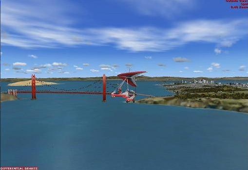
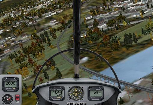
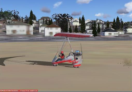
The Golden Gate bridge, shown in the first image below, is not an extrusion bridge, but a specific library object created by an artist. Extrusion bridges, such as the one shown in the second image below, are simple gantry type bridges without towers, suspension cables, or any specific recognizable features. There are around 55,000 extrusion bridges in Flight Simulator X, whereas there is only a small number of specifically created recognizable bridges. Both types of bridge can take moving traffic, this is set by vector data (described in the Terrain and Scenery documentation) though both require platforms to elevate the level of the traffic above the surface of the water. For library objects, the platform is set in the model (see the notes for the Attach Point Tool in Using Modeling Tools) and for extrusion bridges the platform is defined in extrusions.xml. Extrusion bridges can be excluded by use of the ExclusionRectangle element. Also, the rendering of these bridges in the simulation is sensitive to the Scenery Complexity slider, not the Autogen Slider, nor Autogen exclusion mechanisms.
 |
 |
The information entered in the XML for the BGL compiler is referenced in the Extrusions.xml file. The following table shows the entries that should be made for an extrusion bridge in extrusions.xml.
Element |
Description |
Example |
| Extrusion id | GUID identifying this type of extrusion bridge. This will be the value set in extrusionProfile attribute. | <Extrusion id="{55959300-bb2d-4b75-8d6a-934a0fe8f777}"> |
| FriendlyName | This string is mainly for easy identification of the extrusion, but is also used in the Config editor tools described in the autogen documentation. | <FriendlyName>RailRoad Bridge Double Girder 1</FriendlyName> |
| PointList | Defines a cross-section of the bridge, in meters, as pairs of floating point values. Typically the first two entries define the width of the bridge deck, relative to the centerline. In the example given, the bridge deck is 12m wide, defined by Point 0 and Point 1, and there is a guard rail, defined by Point 2 and Point 3, and a drop down section that basically will cover the top of the pillars, defined by Points 4 to 7. |
<Point>-6.000,0.000</Point> <Point>6.000,0.000</Point> <Point>-6.000,1.000</Point> <Point>6.000,1.000</Point> <Point>5.500,0.000</Point> <Point>5.500,-2.000</Point> <Point>-5.500,0.010</Point> <Point>-5.500,-2.000</Point> |
| ExtrusionSegmentList | List of ExtrusionSegments. | |
| ExtrusionSegment | Contains information pertaining to various pairs in the PointList. | |
| PointIndices | Pair of Points that define this segment. The bridge deck in this example. | <PointIndices>0,1</PointIndices> |
| MaterialIndex | The reference number of the material to use, in a list of materials defined by the materialSet attribute. The example will point to the second material in the list, which is indexed from zero. | <MaterialIndex>1</MaterialIndex> |
| TextureWidth | The material texture will be tiled along the length of the extrusion, each tile being this long in meters, 30 meters in the example. | <TextureWidth>30.000</TextureWidth> |
| TextureVExtents | These two floating point values are references into the material texture. If they number from 0.0 to 1.0, that is the segment of the texture to use (from 7/8ths of the width of the texture, to the full width, in the example). These entries can be greater than 1.0. For example values of 0.0, 2.0 will mean that the entire texture is repeated twice across the width of the segment (perhaps repeating road markings twice across the width of a bridge deck). Note that using numbers greater than 1.0 is costly in performance. |
<TextureVExtents>0.875,1.000</TextureVExtents> |
| ExtrusionPlatformSegmentList | A list of ExtrusionPlatformSegments | |
| ExtrusionPlatformSegments | Contains bridge specific information defining the actual platform traffic will use. | |
| PointIndices | A pair from the PointList that are to be used as a platform. Clearly these are the points that define the bridge deck. | <PointIndices>0,1</PointIndices> |
| SurfaceType | One entry from the list of surfaces defined for a Runway entry. These do not affect the appearance of the bridge surface, but do affect special effects (such as on a dirt road) and traffic sounds. | <SurfaceType>PLANKS</SurfaceType> |
This element is part of an ExtrusionBridge element. AltitudeSampleLocationList elements contains exactly two AltitudeSampleLocation elements,
<AltitudeSampleLocationList>

        <!-- AltitudeSampleLocation elements -->

  </AltitudeSampleLocationList>
This element forms part of a AltitudeSampleLocationList. It cannot contain any other elements.
<AltitudeSampleLocation

        latitude = "N47.0"

        longitude = "W123.0"/>
Attribute |
Description |
Acceptable Values |
| lat | Latitude | -90 to +90 degrees Format can be decimal or degrees-minutes-seconds |
| lon | Longitude | -180 to +180 degrees Format can be decimal or degrees-minutes-seconds |
This element is part of an ExtrusionBridge element. PolylineObjectPlacementList elements contain a minimum of zero and a maximum of 255 (typically one - the bridge support pylon) PolylineObjectPlacement elements:
<PolylineObjectPlacementList>

        <!-- PolylineObjectPlacement elements -->

  </PolylineObjectPlacementList>
These elements form part of a PolylineObjectPlacementList element.
<PolylineObjectPlacement

       id = "GUID"
/>
Attribute |
Description |
Acceptable Values |
| id | GUID identifying this object. | GUID in the format:
|
This element is part of an ExtrusionBridge element. PolylinePointList elements contain a minimum of two PolylinePoint elements.
<PolylinePointList>

        <!-- Two or more PolylinePoint elements -->

  </PolylinePointList>
This element forms part of a PolylinePointList. It cannot contain any other elements.
<PolylinePoint

        latitude = "N47.0"

        longitude = "W123.0"

        altitude = "3.0M"/>
Attribute |
Description |
Acceptable Values |
| lat | Latitude | -90 to +90 degrees Format can be decimal or degrees-minutes-seconds |
| lon | Longitude | -180 to +180 degrees Format can be decimal or degrees-minutes-seconds |
| alt | Altitude | Any floating point value. Altitude denotes the vertical displacement of the PolylinePoint from the plane defined by a line segment connecting the terrain at the two AltitudeSampleLocations and a constant elevation line perpendicular to that segment. The intention is to establish the vertical profile of the bridge deck. Altitude may be suffixed by M or F to designate meters or feet. Default is meters. |
This element is part of an ExtrusionBridge element. BankShearList must be empty or contain one BankShearEntry element for each PolylinePoint element present in the PolylinePointList.
<BankShearList>

        <!-- Two or more BankShearEntry elements -->

  </BankShearList>
These elements form part of a BankShearList.
<BankShearEntry

        bank = "-15.0"/>
Attribute |
Description |
Acceptable Values |
| bank | The bank angle of one section of the bridge. | -180.0 to 180.0 |
Facility data is also placed inside of <FSData> elements. The following is a list of the valid facility types and a description of each. The facility data uses references to standard region codes and airline codes. Information on facility codes can be found on the web site for the ICAO organization (www.icao.org, specifically, Document 7910 Location Indicators). Alternative sources may also be available via the Internet.
This element is used to indicate the placement of airport facility information. Airports are placed according to their airport reference point and may contain a large amount of data. When adding Taxi information to an airport, the following elements must all be present and appear in this order: TaxiwayPoint, TaxiwayParking, TaxiName, TaxiwayPath. This element is also allowed to contain Tower, Services, Com, Runway, RunwayAlias, Aprons, ApronEdgeLights, TaxiwaySign, Waypoint, Approach, Ndb, Helipad, Start, Jetway, BlastFence, BoundaryFence, DeleteAirport data and should not be terminated with ‘/>’.
<Airport

        region="North America"

        country="United States"

        state="Illinois"

        city="Peru"

        name="Illinois Valley Regional"

        lat="41.35186742"

        lon="-89.15308328"

        alt="199.33918762"

        magvar="0.0"

        ident="KVYS">

        <!-- Extra   Airport facility data  -->

  </Airport>
Attribute |
Description |
Acceptable Values |
| region (optional) | Global Region of this airport | String (48 characters max) |
| country (optional) | Country/region of this airport | String (48 characters max) |
| state (optional) | State of this airport | String (48 characters max) |
| city (optional) | City of this airport | String (48 characters max) |
| name (optional) | Name of this airport | String (48 characters max) |
| lat | Latitude of this airport | -90 to +90 degrees Format can be decimal or degrees-minutes-seconds |
| lon | Longitude of this airport | -180 to +180 degrees Format can be decimal or degrees-minutes-seconds |
| alt | Altitude of this airport | Any floating point value. Altitude may be suffixed by M or F to designate meters or feet. Default is meters. |
| magvar (optional) | Magnetic variation at the airport to True North in degrees. | -360.0 to 360.0 floating point value. Default = 0.0. East magvar is negative, West magvar is positive. |
| ident | ICAO ident for this airport | String (4 characters max) |
| airportTestRadius | This optional radius will force compiler warnings if any element of the airport is outside of the radius. | Distance in feet, meters or Nautical miles (F, M, N suffix). |
| trafficScalar | The volume of AI traffic that is appropriate for this airport. 1.0 would apply to major airports. | Value between 0.01 and 1.0. |
Jetway elements are part of an airport, and must contain one, and only one, SceneryObject element. One jetway can service at most one parking spot. A jetway will animate (move towards the main exit) when the user presses Ctrl-J and will usually come in to the main exit on the left side of the aircraft. AI controlled aircraft will also trigger the animation of the jetway. To replace jetways at an airport, use the DeleteAirport element with the deleteAllJetways field set to "TRUE", then enter the new jetway elements. Note that all parking spots do not require jetways. Refer also the Jetways modeling document.
<Jetway

        gateName = "GATE_A"

        parkingNumber = "1" >

      <!-- Scenery object  -->

  </Jetway>
Attribute |
Description |
Acceptable Values |
| gateName | Gate or parking spot. | PARKING DOCK, GATE GATE_A to GATE_Z, NONE N_PARKING NE_PARKING NW_PARKING SE_PARKING S_PARKING SW_PARKING W_PARKING E_PARKING |
| parkingNumber | Both a gateName and parkingNumber are required to uniquely identify a parking location. | Non-negative integer. |
BlastFence and BoundaryFence elements are part of an airport, and must contain at least two Vertex elements. To replace fences at an airport, use the DeleteAirport element with the deleteAllBlastFences or deleteAllBoundaryFences fields set to "TRUE", then enter the new fence elements.
<BlastFence>

      instanceId = "GUID"

      profile = "GUID" >

      <!-- Two or more Vertex elements -->

  </BlastFence>
For example:
<BoundaryFence   instanceId="{guid}"   profile="{guid}"   >

       <Vertex lat="56.95721658"   lon="-158.63880255" />

       <Vertex lat="56.95649892"   lon="-158.64139507" />

       <Vertex lat="56.95643874"   lon="-158.64143179" />

       <Vertex lat="56.95638593"   lon="-158.64147906" />

       <Vertex lat="56.95634419"   lon="-158.64152952" />

       <Vertex lat="56.95617823"   lon="-158.64175382" />

       <Vertex lat="56.95362527"   lon="-158.63877271" />

       <Vertex lat="56.95253646"   lon="-158.64211307" />

       <Vertex lat="56.96425872"   lon="-158.65580206" />

</BoundaryFence>
Attribute |
Description |
Acceptable Values |
| instanceId | Optional GUID identifying this element. | GUID in the format:
|
| profile | Required, a GUID identifying the type of fence from the Extrusions.xml file. | GUID in the format:
|
 |
The boundary fence at Boeing Field is just visible underneath the wing of the aircraft. |
There are two relevant entries in the extrusions.xml for each blast or boundary fence. In a section Extrusions.Fences there is an entry with the following attributes:
Element |
Description |
Example |
| FenceProfile id | This is the GUID that matches the profile attribute. | <FenceProfile id="{02D65B05-F752-47a3-83AF-D570243EB3EE}"> |
| FriendlyName | A description of the fence, also used by the Autogen Config editor tools. | <FriendlyName>5 Meter Chain-link</FriendlyName> |
| MaterialSetReference | GUID of the material to use, defined in the Materials.xml file. | <MaterialSetReference>{2D6ED02C-51CF-43D2-9EBD-A5E86284830B}</MaterialSetReference> |
| ExtrusionReference | GUID internal to the extrusions.xml file, identifying the key physical attributes of the fence, described in the following table. | <ExtrusionReference>{9093AC0C-FB5E-433D-9E2B-C19D637EA664}</ExtrusionReference> |
The Extrusion entry in Extrusions.xml contains the following entries for each fence:
Element |
Description |
Example |
| Extrusion id | GUID identifying this type of extrusion fence. This will be the value set in the ExtrusionReference attribute. | <Extrusion id="{9093AC0C-FB5E-433d-9E2B-C19D637EA664}"> |
| FriendlyName | This string is mainly for easy identification of the extrusion. | <FriendlyName>Fence vertical 2 meter extrusion</FriendlyName> |
| PointList | Defines a cross-section of the fence, in meters, as pairs of floating point values. |
<Point>0.000,0.000</Point> |
| ExtrusionSegmentList | List of ExtrusionSegments. | |
| ExtrusionSegment | Contains information pertaining to various pairs in the PointList. | |
| PointIndices | Pair of Points that define this segment. For a fence this is usually just points 0 and 1. | <PointIndices>0,1</PointIndices> |
| TextureWidth | The texture width typically matches the height of the fence. | <TextureWidth>2.000</TextureWidth> |
| TextureVExtents | These two floating point values are references into the material texture. If they number from 0.0 to 1.0, that is the segment of the texture to use (the full width of the texture, in the example). These entries can be greater than 1.0. For example values of 0.0, 2.0 will mean that the entire texture is repeated twice up the height of the fence. Note that using numbers greater than 1.0 is costly in performance. |
<TextureVExtents>0.000,1.000</TextureVExtents> |
This element is used to delete an airport or part of an airport and potentially replace with new information. This element is not allowed to contain other data and must be terminated with ‘/>’.
<DeleteAirport

        deleteAllApproaches = "TRUE"

        deleteAllApronLights = "TRUE"

        deleteAllAprons = "TRUE"

        deleteAllFrequencies = "TRUE"

        deleteAllHelipads = "TRUE"

        deleteAllRunways = "TRUE"

        deleteAllStarts = "TRUE"

        deleteAllTaxiways = "TRUE"

        deleteAllBlastFences = "TRUE"

        deleteAllBoundaryFences = "TRUE"

        deleteAllControlTowers = "TRUE"

        deleteAllJetways = "TRUE"/>
For example, to replace all the jetways at an airport with a new model, enter the following code:
<Airport

        region="North America"

          country="United States"

          state="Illinois"

        city="Peru"

        name="Illinois Valley Regional"

        lat="41.35186742"

          lon="-89.15308328"

          alt="199.33918762"

          magvar="0.0"

        ident="KVYS">


     <DeleteAirport

            deleteAllJetways = "TRUE"/>


     <Jetway

            gateName = "GATE_A"

              parkingNumber = "1" >

            <!-- Scenery   object -->

       </Jetway>


     <Jetway

            gateName = "GATE_B"

            parkingNumber = "1" >

            <!-- Scenery   object -->

       </Jetway>


     // Add as many Jetway elements as needed


</Airport>
Attribute |
Description |
Acceptable Values |
| deleteAllApproaches (optional) | Boolean to delete all approaches | TRUE or FALSE |
| deleteAllApronLights(optional) | Boolean to delete all apron lights | TRUE or FALSE |
| deleteAllAprons(optional) | Boolean to delete all aprons | TRUE or FALSE |
| deleteAllFrequencies(optional) | Boolean to delete all frequencies | TRUE or FALSE |
| deleteAllHelipads(optional) | Boolean to delete all helipads | TRUE or FALSE |
| deleteAllRunways(optional) | Boolean to delete all runways | TRUE or FALSE |
| deleteAllStarts(optional) | Boolean to delete all starts | TRUE or FALSE |
| deleteAllTaxiways(optional) | Boolean to delete all taxiways | TRUE or FALSE |
| deleteAllBlastFences(optional) | Boolean to delete all blast fences | TRUE or FALSE |
| deleteAllBoundaryFences(optional) | Boolean to delete all boundary fences | TRUE or FALSE |
| deleteAllControlTowers(optional) | Boolean to delete all control towers | TRUE or FALSE |
| deleteAllJetways(optional) | Boolean to delete all jetways | TRUE or FALSE |
This element is used to delete a runway from an airport. This element is not allowed to contain other data and must be terminated with ‘/>’.
<DeleteRunway

        surface="ASPHALT"

        number="18"

        designator="NONE"/>
Attribute |
Description |
Acceptable Values |
| surface | Surface type of runway | ASPHALT BITUMINOUS BRICK CLAY CEMENT CONCRETE CORAL DIRT GRASS GRAVEL ICE MACADAM OIL_TREATED, PLANKS SAND SHALE SNOW STEEL_MATS TARMAC UNKNOWN WATER |
| number | Runway number | 00 to 09 0 to 36 EAST NORTH NORTHEAST NORTHWEST SOUTH SOUTHEAST SOUTHWEST WEST |
| designator (optional) | Runway designator | NONE C CENTER L LEFT R RIGHT W WATER A B |
This element is used to delete a start location from an airport. This element is not allowed to contain other data and must be terminated with ‘/>’.
<DeleteStart

        type="RUNWAY"

        number="18"

        designator="NONE"/>
Attribute |
Description |
Acceptable Values |
| type | Type of start | RUNWAY HELIPAD WATER |
| number | Runway number | 00 to 09 0 to 36 EAST NORTH NORTHEAST NORTHWEST SOUTH SOUTHEAST SOUTHWEST WEST |
| designator (optional) | Runway designator | NONE C CENTER L LEFT R RIGHT W WATER A B |
This element is used to delete a communication frequency from an airport. This element is not allowed to contain other data and must be terminated with ‘/>’.
<DeleteFrequency

        frequency = "122.85"

        type="CENTER" />
Attribute |
Description |
Acceptable Values |
| frequency | Frequency (in MHz) to be deleted | 108.0 to 136.992 floating point value |
| type | Type of frequency | APPROACH ASOS ATIS AWOS CENTER CLEARANCE CLEARANCE_PRE_TAXI CTAF DEPARTURE FSS GROUND MULTICOM REMOTE_CLEARANCE_DELIVERY TOWER UNICOM |
This element is used to place a tower location at an airport. This element is not allowed to contain other data and must be terminated with ‘/>’.
<Tower

        lat="41.35186742"

        lon="-89.15308328"

        alt="199.33918762"/>
Attribute |
Description |
Acceptable Values |
| lat | Latitude of tower. Optional. | -90 to +90 degrees Format can be decimal or degrees-minutes-seconds |
| lon | Longitude of tower. Optional. | -180 to +180 degrees Format can be decimal or degrees-minutes-seconds |
| alt | Altitude of tower. Optional. | Any floating point value. Altitude may be suffixed by M or F to designate meters or feet. Default is meters. |
This element is used to add a runway to an airport. This element is allowed to contain the following elements, which must occur in the following order Markings, Lights, OffsetThreshold, BlastPad, Overrun, ApproachLights, VASI, ILS, RunwayStart data and should not be terminated with ‘/>’.
Note that runways specified with a width less than 2 feet are not rendered (the minimum width that can be specified is 1 foot). Use the "WATER" setting for the runway surface if the runway is a seaplane landing area.
Note also that third-party runway textures are not supported in Flight Simulator X.
<Runway

      lat="41.35184943"

      lon="-89.15309158"

      alt="199.33918762"

      surface="ASPHALT"

      heading="179.580000"

      length="6000F"

      width="100F"

      number="18"

      designator="NONE"

      patternAltitude="304.799988"

      primaryTakeoff="YES"

      primaryLanding="YES"

      primaryPattern="LEFT"

      secondaryTakeoff="YES"

      secondaryLanding="YES"

      secondaryPattern="LEFT">

      <!-- Runway data here -->

</Runway>
Attribute |
Description |
Acceptable Values |
| lat | Latitude of the center point of the runway. | -90 to +90 degrees Format can be decimal or degrees-minutes-seconds |
| lon | Longitude of the center point of the runway | -180 to +180 degrees Format can be decimal or degrees-minutes-seconds |
| alt | Altitude of the center point of the runway. Note that sloping runways are not supported the entire runway will be at this altitude. This may involve some "landscaping" for a new runway that is not replacing an old one. See the Terrain SDK for more details. | Any floating point value. May be suffixed by M or F to designate meters or feet. Default is meters. |
| surface | Runway surface type | ASPHALT BITUMINOUS BRICK CLAY CEMENT CONCRETE CORAL DIRT GRASS GRAVEL ICE MACADAM OIL_TREATED, PLANKS SAND SHALE SNOW STEEL_MATS TARMAC UNKNOWN WATER |
| heading | Runway heading | 0-360 floating point |
| length | Length of runway | Any floating point value. May be suffixed by M or F to designate meters or feet. Default is meters. |
| width | Width of runway | Any floating point value. May be suffixed by M or F to designate meters or feet. Default is meters. |
| number | Runway number | 00 to 09 0 to 36 EAST NORTH NORTHEAST NORTHWEST SOUTH SOUTHEAST SOUTHWEST WEST |
| designator (optional) | Runway designator. If this value is set, the secondaryDesignator (the runway in the opposite direction) is set automatically. Do not enter both a designator and primaryDesignator. | NONE C CENTER L LEFT R RIGHT W WATER A B |
| primaryDesignator | If this value is set, the secondaryDesignator is not set, but should be specified next. | Same values as designator. |
| secondaryDesignator | Opposite designator to primary designator. | Same values as designator. |
| patternAltitude (optional) | Pattern altitude for this runway | Any floating point value. May be suffixed by M or F to designate meters or feet. Default is meters. |
| primaryTakeoff (optional) | Boolean indicating that the primary direction for the runway can be used for takeoff. | TRUE, FALSE. Default is TRUE. Note the use of YES/NO in the example above. These two words are synonymous with TRUE/FALSE. |
| primaryLanding (optional) | Boolean indicating that the primary direction for the runway can be used for landing. | TRUE, FALSE. Default is TRUE |
| primaryPattern (optional) | Indication of pattern orientation for primary heading (optional) | LEFT, RIGHT. Default is LEFT. |
| secondaryTakeoff (optional) | Boolean indicating that the secondary direction for the runway can be used for takeoff. | TRUE, FALSE. Default is TRUE |
| secondaryLanding (optional) | Boolean indicating that the primary direction for the runway can be used for landing. | TRUE, FALSE. Default is TRUE |
| secondaryPattern (optional) | Indication of pattern orientation for secondary heading (optional) | LEFT, RIGHT. Default is LEFT. |
| primaryMarkingBias | Bias from the end of the runway for primary markings. | Distance in feet, nautical miles, or meters (F, N or M suffix). |
| secondaryMarkingBias | Bias from the end of the runway for secondary markings. | Distance in feet, nautical miles, or meters (F, N or M suffix). |
This element is used to add markings to an airport runway. This element is not allowed to contain other data and must be terminated with ‘/>’.
<Markings

        edges="TRUE"

        threshold="TRUE"

        fixedDistance="TRUE"

        touchdown="TRUE"

        dashes="TRUE"

        ident="TRUE"

        precision="TRUE"

        edgePavement="TRUE"

        singleEnd="TRUE"

        primaryClosed="TRUE"

        secondaryClosed="TRUE"

        primaryStol="TRUE"

        secondaryStol="TRUE"/>
Attribute |
Description |
Acceptable Values |
| alternateThreshold | Set to TRUE to indicate international rather than US Threshold markings. | TRUE, FALSE |
| alternateTouchdown | Set to TRUE to indicate international rather than US Touchdown markings. | TRUE, FALSE |
| alternateFixedDistance | Set to TRUE to indicate international rather than US Fixed Distance markings. | TRUE, FALSE |
| alternatePrecision | Set to TRUE to indicate international rather than US Precision markings. | TRUE, FALSE |
| leadingZeroIdent | Set to TRUE to indicate runway numbers have a leading zero (for runway numbers 0 to 9). | TRUE, FALSE |
| noThresholdEndArrows | Set to TRUE to ignore Threshold End Arrows. | TRUE, FALSE |
| edges | Runway has edge lines | TRUE, FALSE |
| threshold | Runway has threshold marks | TRUE, FALSE |
| fixed | Runway has fixed distance marks | TRUE, FALSE |
| touchdown | Runway has touchdown marks | TRUE, FALSE |
| dashes | Runway has dashed line down center | TRUE, FALSE |
| ident | Runway has number and designator | TRUE, FALSE |
| precision | Runway has precision markings | TRUE, FALSE |
| edgePavement | Runway has pavement past edge lines | TRUE, FALSE |
| singleEnd | Runway is single-ended with no markings on secondary end | TRUE, FALSE |
| primaryClosed | Primary end is closed with X | TRUE, FALSE |
| secondaryClosed | Secondary is closed with X | TRUE, FALSE |
| primaryStol | Primary end STOL | TRUE, FALSE |
| secondaryStol | Secondary end STOL | TRUE, FALSE |
This element is used to add lights to an airport runway. This element is not allowed to contain other data and must be terminated with ‘/>’.
<Lights

        center="LOW"

        edge="LOW"

        centerRed="TRUE"/>
Attribute |
Description |
Acceptable Values |
| center | Center runway lights | NONE (default) LOW MEDIUM HIGH |
| edge | Edge runway lights | NONE (default) LOW MEDIUM HIGH |
| centerRed | Boolean indicating that the last part of the center line lights are RED/WHITE and then RED | TRUE, FALSE |
This element is used to add an offset threshold to an airport runway. This element is not allowed to contain other data and must be terminated with ‘/>’.
<OffsetThreshold

        end="PRIMARY"

        length="250F"

        width="200F"

        surface="ASPHALT"/>
Attribute |
Description |
Acceptable Values |
| end | Which end of the runway that the offset threshold applies to. | PRIMARY SECONDARY |
| length | Length of pavement. This length is included in the main runway length. | Any floating point value. May be suffixed by M or F to designate meters or feet. Default is meters. |
| width (optional) | Width of pavement (if different from runway) | Any floating point value. May be suffixed by M or F to designate meters or feet. Default is meters. |
| surface (optional) | Surface type | ASPHALT BITUMINOUS BRICK CLAY CEMENT CONCRETE CORAL DIRT GRASS GRAVEL ICE MACADAM OIL_TREATED, PLANKS SAND SHALE SNOW STEEL_MATS TARMAC UNKNOWN WATER |
This element is used to add a blast pad to an airport runway. This element is not allowed to contain other data and must be terminated with ‘/>’.
<BlastPad

        end="PRIMARY"

        length="250F"

        width="100F"

        surface="ASPHALT"/>
Attribute |
Description |
Acceptable Values |
| end | Which end of the runway that the blast pad applies to. | PRIMARY SECONDARY |
| length | Length of blast pad. This value is added to main runway length. | Any floating point value. May be suffixed by M or F to designate meters or feet. Default is meters. |
| width (optional) | Width of blast pad if different from runway. | Any floating point value. May be suffixed by M or F to designate meters or feet. Default is meters. |
| surface (optional) | Surface of blast pad if different from the runway. | ASPHALT BITUMINOUS BRICK CLAY CEMENT CONCRETE CORAL DIRT GRASS GRAVEL ICE MACADAM OIL_TREATED, PLANKS SAND SHALE SNOW STEEL_MATS TARMAC UNKNOWN WATER |
This element is used to add an overrun to an airport runway. This element is not allowed to contain other data and must be terminated with ‘/>’.
<Overrun

        end="PRIMARY"

         length="250F"

         width="100F"

         surface="DIRT"/>
Attribute |
Description |
Acceptable Values |
| end | Which end of the runway that the blast pad applies to. | PRIMARY SECONDARY |
| length | Length of overrun. This value is added to main runway length. | Any floating point value. May be suffixed by M or F to designate meters or feet. Default is meters. |
| width (optional) | Width of overrun if different from the runway. | Any floating point value. May be suffixed by M or F to designate meters or feet. Default is meters. |
| surface (optional) | Surface of overrun if different from the runway. | ASPHALT BITUMINOUS BRICK CLAY CEMENT CONCRETE CORAL DIRT GRASS GRAVEL ICE MACADAM OIL_TREATED, PLANKS SAND SHALE SNOW STEEL_MATS TARMAC UNKNOWN WATER |
This element is used to add approach lights to an airport runway. This element is not allowed to contain other data and must be terminated with ‘/>’.
<ApproachLights

        end="PRIMARY"

        system="ALSF2"

        strobes="11"

        reil="TRUE"

        touchdown="TRUE"

        endLights="TRUE"/>
Attribute |
Description |
Acceptable Values |
| end | End of runway that the lights are for | PRIMARY SECONDARY |
| system (optional) | Type of approach light system | NONE ALSF1 ALSF2 CALVERT CALVERT2 MALS MALSF MALSR ODALS RAIL SALS SALSF SSALF SSALR SSALS |
| strobes (optional) | Number of sequenced strobes | Non-negative integer. Default is zero. |
| reil (optional) | Boolean indicating that runway has runway end identifier lights | TRUE, FALSE |
| touchdown (optional) | Boolean indicating that runway has touchdown lights | TRUE, FALSE |
| endLights (optional) | Boolean indicating that runway has end lights | TRUE, FALSE |
This element is used to add a VASI to an airport runway. This element is not allowed to contain other data and must be terminated with ‘/>’.
<Vasi

        end="PRIMARY"

        type="VASI21"

        side="LEFT"

        biasX="50F"

        biasZ="4000F"

        spacing="250F"

        pitch="3.10"/>
Attribute |
Description |
Acceptable Values |
| end | End of runway that the VASI is for | PRIMARY SECONDARY |
| type | Type of Vasi. | PAPI2 (2 light PAPI) PAPI4 (4 light PAPI) PVASI (Pulsating VASI) TRICOLOR Tri Color VASI TVASI colored VASI in a shared-T shape VASI21 2 rows, 1 box/row VASI22 2 rows, 2 boxes/row VASI23 2 rows, 3 boxes/row VASI31 3 rows, 1 box/row VASI32 3 rows, 2 boxes/row VASI33 3 rows, 3 boxes/row (far row has only two boxes, 8 light system) BALL (presently remapped to PVASI) APAP (panels) PANELS (presently remapped to PAP2) |
| side | Side of runway that the lights are on | LEFT RIGHT |
| biasX | Distance from runway center to light. | Floating point value, default units are meters |
| biasZ | Distance from runway center to light. | Floating point value, default units are meters |
| spacing | Distance between light rows. | Positive floating point value, default units are meters |
| pitch | Approach angle in degrees. | 0.0 to 10.0 floating point value |
This element is used to add an ILS to an airport runway. This element is allowed to contain GlideSlope, DME and VisualModel data and should not be terminated with ‘/>’.
<Ils

        lat="41.35184943"

        lon="-89.15309158"

        alt="199.33918762"

        heading="359.580000"

        frequency="110.3500"

        end="PRIMARY"

        range="12000"

        magvar="0.0"

        ident="ABDY"

        width="5.00"

        name="Some Airport ILS"

        backCourse="FALSE">

          <!-- Optional elements go here -->


  </Ils>
Attribute |
Description |
Acceptable Values |
| lat | Latitude of object | -90 to +90 degrees Format can be decimal or degrees-minutes-seconds |
| lon | Longitude of object | -180 to +180 degrees Format can be decimal or degrees-minutes-seconds |
| alt | Altitude of object | Any floating point value. May be suffixed by M or F to designate meters or feet. Default is meters. |
| heading | Heading of main ILS beam | 0.0 to 360.0 floating point value |
| frequency | ILS Frequency in MHz | 108.0 to 136.992 floating point value |
| end | End of runway for this ILS | PRIMARY SECONDARY |
| range (optional) | Range of ILS in meters or nautical miles. Default is 27 nautical miles if not specified. | Use the letter "N" to specify a distance in nautical miles. For example, the default is "27N" If no letter is entered the measurement will be in meters. |
| magvar | Magnetic variation at the ILS to True North in degrees. | -360.0 to 360.0 floating point value. Default = 0.0. East magvar is negative, West magvar is positive. |
| ident | ICAO ident for this ILS | String (5 characters max) |
| width (optional) | Localizer beam width in degrees Default is 5 degrees. | 0.0 to 360.0 floating point value |
| name (optional) | Friendly name for ILS | String (48 characters max) |
| backCourse (optional) | Boolean indicating that this ILS has a back course | TRUE, FALSE |
This element is used to add a glide slope to an ILS. This element is not allowed to contain other data and must be terminated with ‘/>’.
<GlideSlope

        lat="19 22 15.48"

        lon="48.12345"

        alt="703.65F"

        pitch="3.00"

        range="20N"/>
Attribute |
Description |
Acceptable Values |
| lat | Latitude of object | -90 to +90 degrees Format can be decimal or degrees-minutes-seconds |
| lon | Longitude of object | -180 to +180 degrees Format can be decimal or degrees-minutes-seconds |
| alt | Altitude of object | Any floating point value. May be suffixed by M or F to designate meters or feet. Default is meters. |
| pitch | Pitch of glide slope | 0.0 to 360.0 floating point value |
| range | Range of glide slope. Default is 27 nautical miles if not specified. | Use the letter "N" to specify a distance in nautical miles. For example, the default is "27N" If no letter is entered the measurement will be in meters. |
This element is used to add a single visual model to number of elements, including Ndb, ILS and VOR. This element is allowed to contain Bias data and should not be terminated with ‘/>’.
<VisualModel

        heading="45.0"

        imageComplexity="NORMAL"

        name="GUID">

        <!-- Optional BiasXYZ goes here -->

  </VisualModel>
Attribute |
Description |
Acceptable Values |
| heading (optional) | Heading of model placement | 0.0 to 360.0 floating point value |
| imageComplexity (optional) | Minimum image complexity setting for the objects to appear. For example, objects set at NORMAL will appear if the setting is DENSE, but not appear if the setting is SPARSE. | VERY_SPARSE SPARSE NORMAL DENSE VERY_DENSE |
| name | GUID of desired object | GUID in the format:
|
| instanceId | Optional GUID used to identify this instance of the VisualModel element. | GUID in the format:
|
This element is used to add a start location for a runway. This location will show up on the Go To Airport dialog. This element is not allowed to contain other data and must be terminated with ‘/>’.
<RunwayStart

        type="RUNWAY"

        lat="41.45240683"

        lon="-87.01929230"

        alt="235.00079346"

        heading="90.130000"

        end="PRIMARY"/>
Attribute |
Description |
Acceptable Values |
| type (optional) | Type of start location | RUNWAY |
| lat | Latitude of object | -90 to +90 degrees Format can be decimal or degrees-minutes-seconds |
| lon | Longitude of object | -180 to +180 degrees Format can be decimal or degrees-minutes-seconds |
| alt | Altitude of object | Any floating point value. May be suffixed by M or F to designate meters or feet. Default is meters. |
| heading | Heading applied to object | 0.0 to 360.0 floating point value |
| end (optional) | End of runway that this start location is for | PRIMARY SECONDARY |
This element is used when replacing components inside of an airport (like taxiways), but the intent is not to replace the actual runways. This element serves as a note to the compiler that the old runway definition is to be preserved. This element is not allowed to contain other data and must be terminated with ‘/>’.
<RunwayAlias

        number="1"

        designator="RIGHT"/>
Attribute |
Description |
Acceptable Values |
| number | Runway number | 00 to 09 0 to 36 EAST NORTH NORTHEAST NORTHWEST SOUTH SOUTHEAST SOUTHWEST WEST |
| designator | Runway designator | NONE C CENTER L LEFT R RIGHT W WATER A B |
This element is used to add a start location for a runway or an airport in general. This location will show up on the Go To Airport dialog. This element is not allowed to contain other data and must be terminated with ‘/>’.
<Start

        type="RUNWAY"

        lat="41.45240683"

        lon="-87.01929230"

        alt="235.00079346"

        heading="90.130000"

        number="10"

        designator="NONE"/>
Attribute |
Description |
Acceptable Values |
| type (optional) | Type of start | RUNWAY |
| lat | Latitude of start | -90 to +90 degrees Format can be decimal or degrees-minutes-seconds |
| lon | Longitude of start | -180 to +180 degrees Format can be decimal or degrees-minutes-seconds |
| alt | Altitude of start | Any floating point value. May be suffixed by M or F to designate meters or feet. Default is meters. |
| heading | Heading applied to object | 0.0 to 360.0 floating point value |
| number (optional) | Runway number | 00 to 09 0 to 36 EAST NORTH NORTHEAST NORTHWEST SOUTH SOUTHEAST SOUTHWEST WEST |
| designator (optional) | Runway designator | NONE C CENTER L LEFT R RIGHT W WATER A B |
This element is used to add a helipad to an airport. This element is not allowed to contain other data and must be terminated with ‘/>’.
<Helipad

        lat="N47 26.00"

        lon="W122 18.38"

        alt="432.7F"

        surface="BRICK"

        heading="0"

        length="200F"

        width="100F"

        type="CIRCLE"

        closed="FALSE"

        transparent="FALSE"/>
Attribute |
Description |
Acceptable Values |
| lat | Latitude of center of helipad. | -90 to +90 degrees Format can be decimal or degrees-minutes-seconds |
| lon | Longitude of center of helipad. | -180 to +180 degrees Format can be decimal or degrees-minutes-seconds |
| alt | Altitude of center of helipad. | Any floating point value. May be suffixed by M or F to designate meters or feet. Default is meters. |
| surface | Helipad surface type | ASPHALT BITUMINOUS BRICK CLAY CEMENT CONCRETE CORAL DIRT GRASS GRAVEL ICE MACADAM OIL_TREATED, PLANKS SAND SHALE SNOW STEEL_MATS TARMAC UNKNOWN WATER |
| heading | Helipad heading | 0.0 to 360.0 floating point value |
| length | Length of helipad | Any floating point value. May be suffixed by M or F to designate meters or feet. Default is meters. |
| width | Width of helipad | Any floating point value. May be suffixed by M or F to designate meters or feet. Default is meters. |
| type | Type of helipad. Note that if you enter type as CIRCLE or SQUARE and the length and width are not identical, then the shape of the helipad will be an ellipse or rectangle, respectively. | NONE CIRCLE H MEDICAL SQUARE |
| closed (optional) | Boolean indicating whether the helipad is closed (so not available as a landing site). | TRUE, FALSE |
| transparent (optional) | Boolean indicating that the helipad should be drawn without pavement (markings only) | TRUE, FALSE |
| red (optional) | Red color component of helipad markings. Note that the red, green, blue fields are not implemented. | Integer 0-255 |
| green (optional) | Green color component | Integer 0-255 |
| blue (optional) | Blue color component | Integer 0-255 |
This element is used to add a COM frequency to an airport. This element is not allowed to contain other data and must be terminated with ‘/>’.
<Com

          frequency="135.9000"

          type="CENTER"

          name="CHICAGO"/>
Attribute |
Description |
Acceptable Values |
| frequency | Frequency for COM in MHz | 108.0 to 136.992 floating point value |
| type | Type of COM frequency | APPROACH ASOS ATIS AWOS CENTER CLEARANCE CLEARANCE_PRE_TAXI CTAF DEPARTURE FSS GROUND MULTICOM REMOTE_CLEARANCE_DELIVERY TOWER UNICOM |
| name | Friendly name for COM frequency | String (48 characters max) |
This element is used to add an approach to an airport. Approaches are made up of three components, which must occur in the following order: ApproachLegs, MissedApproachLegs, and Transition elements. This element should not be terminated with ‘/>’.
<Approach

          type="NDB"

          runway="3"

          designator="LEFT"

          suffix="A"

          gpsOverlay="TRUE"

          fixType="VOR"

          fixRegion="K9"

          fixIdent="IDENT">

          altitude="20"

          heading="123.62"

          missedAltitude="1234">

        <!-- Add approach components here -->

  </Approach>
Attribute |
Description |
Acceptable Values |
| type | Type of Approach | GPS ILS LDA LOCALIZER LOCALIZER_BACKCOURSE NDB NDBDME RNAV SDF VOR VORDME |
| runway (optional) | Runway Number Approach is attached to | 00 to 09 0 to 36 EAST NORTH NORTHEAST NORTHWEST SOUTH SOUTHEAST SOUTHWEST WEST |
| designator (optional) | Runway designator | NONE C CENTER L LEFT R RIGHT W WATER A B |
| suffix (optional) | One Char identifier | One character |
| gpsOverlay (optional) | Has a GPS overlay. | TRUE FALSE (default) |
| fixType | Type of FAF | NDB TERMINAL_NDB TERMINAL_WAYPOINT VOR WAYPOINT |
| fixRegion | Station Region of the FAF | String (2 characters max) |
| fixIdent | Station Ident of the FAF | String (5 characters max) |
| altitude | Altitude for final approach in meters. | Floating point value. |
| heading | Final course heading start | 0.0 to 360.0 floating point value |
| missedAltitude | Missed approach altitude in meters | Floating point value |
This element is used to add approach legs to an airport approach. ApproachLegs have no attributes and are used as a container to hold a list of Leg elements, which describe the individual segments of the approach. This element should not be terminated with ‘/>’.
<ApproachLegs>

        <!-- add Leg elements here -->

</ApproachLegs>This element is used to add legs for a missed approach path to an airport approach. MissedApproachLegs have no attributes and are used as a container to hold a list of Leg elements, which describe the individual segments of the missed approach. This element should not be terminated with ‘/>’.
<MissedApproachLegs>

        <!-- add Legs elements here -->

  </MissedApproachLegs>
This element is used to add transitions to an airport approach. A Transition has some attributes and contains a list of DmeArc and/or TransitionLegs elements If both are present the DmeArc must be entered first. The Leg and DmeArc elements describe the individual segments of the transition. This element should not be terminated with ‘/>’.
<Transition

        transitionType="FULL"

        fixType="WAYPOINT"

        fixRegion="K9"

        fixIdent="IDENT"

        altitude="20">

        <!-- add DmeArc and/or TransitionLegs elements  here -->

  </Transition>
Attribute |
Description |
Acceptable Values |
| transitionType | Transition Type | FULL = full procedure DME = DME arc transition |
| fixType | Type of IAF | NDB TERMINAL_NDB TERMINAL_WAYPOINT VOR WAYPOINT |
| fixRegion | Station region of the IAF | 2-character region code |
| fixIdent | Station Ident of the IAF. | String (5 characters max) |
| Altitude | Altitude of the first leg of the transition in meters. | Floating point value.. |
This element is used to add legs to approaches. The specific information required to define the leg depends on the type. This element is not allowed to contain other data and must be terminated with ‘/>’. All of the leg types either require, or can take as optional, an altitude code letter (the altitudeDescriptor field) and either one or two altitude values. The following table shows the range of values and how they are interpreted.
<Leg

        type="AF"

        fixType="WAYPOINT"

        fixRegion="K1"

        fixIdent="ORD"

        flyOver="TRUE"

        turnDirection="L"

        recommendedType="VOR"

        recommendedRegion="K1"

        recommendedIdent="ORD"

        theta="125.2"

        rho="1.2"

        trueCourse="166.1"

        altitudeDescriptor="+"

        altitude1="1000.0"/>
Attribute |
Description |
Acceptable Values |
| type | Type of Leg. | AF CA CD CF CI CR DF FA FC FD FM HA HF HM IF PI RF TF VA VD VI VM VR |
| fixType | Type of Fix. | NDB TERMINAL_NDB TERMINAL_WAYPOINT VOR WAYPOINT |
| fixRegion | 2 character region code | 2-character region code |
| fixIdent | 5 character ident | String (5 characters max) |
| flyOver | Boolean indicating whether this leg is intended to fly over the given point, or fly by the point. | TRUE = fly over FALSE = fly by (default) |
| turnDirection | Turn direction supplied for this leg. | L (left) R (right) E (either, default) |
| recommendedType | Type of target for this leg. | NDB TERMINAL_NDB TERMINAL_WAYPOINT VOR WAYPOINT RUNWAY,LOCALIZER |
| recommendedRegion | Region code | 2 character string |
| recommendedIdent | Ident | 5 character string maximum |
| theta | Heading in degrees | 0.0 to 360.0 floating point value |
| rho | Distance | Floating point value, default units are meters, use the suffix "N" to specify nautical miles. |
| trueCourse | True North Course in degrees. Do not enter a value for magneticCourse | 0.0 to 360.0 floating point value |
| magneticCourse | Magnetic North Course in degrees. Do not enter a value for trueCourse | 0.0 to 360.0 floating point value |
| distance | Distance. Do not enter a value for time. | Floating point value, default units are meters, suffix with "N" for nautical miles. |
| time | Time in minutes. Do not enter a value for distance. | Floating point value |
| altitudeDescriptor | Value that describes how altitude1 and altitude2 are interpreted. | See altitudeDescriptor table above. |
| altitude1 | Altitude1 | Floating point value. Default units are meters |
| altitude2 | Altitude2 | Floating point value. Default units are meters. |
The following tables show the different Leg types and their associated Required (R) and Optional (O) attributes.
| AF | CA | CD | CF | CI | CR | DF | FA | FC | FD | FM | HA | |
| fixType | R | R | R | R | R | R | R | R | ||||
| fixRegion | R | R | R | R | R | R | R | R | ||||
| fixIdent | R | R | R | R | R | R | R | R | ||||
| flyOver | O | R | O | O | R | R | O | |||||
| turnDirection | R | O | O | O | O | O | O | O | O | O | O | O |
| recommendedType | R | R | R | O | R | O | R | R | R | R | O | |
| recommendedRegion | R | R | R | O | R | O | R | R | R | R | O | |
| recommendedIdent | R | R | R | O | R | O | R | R | R | R | O | |
| theta | R | R | O | R | R | R | R | O | ||||
| rho | R | R | O | R | R | R | R | O | ||||
| trueCourse * | R | R | R | R | R | R | R | R | R | R | R | |
| magneticCourse * | R | R | R | R | R | R | R | R | R | R | R | |
| distance** | R | R | R | R | R | R | R | |||||
| time** | R | |||||||||||
| altitudeDescriptor | O | R | O | O | O | O | O | O | O | O | O | R |
| altitude1 | O | R | O | O | O | O | O | O | O | O | O | R |
| altitude2 | O | O | O | O | O | O | O | O |
| HF | HM | IF | PI | RF | TF | VA | VD | VI | VM | VR | |
| fixType | R | R | R | R | R | R | O | ||||
| fixRegion | R | R | R | R | R | R | O | ||||
| fixIdent | R | R | R | R | R | R | O | ||||
| flyOver | O | O | O | O | |||||||
| turnDirection | O | O | R | R | O | O | O | O | O | O | |
| recommendedType | O | O | O | R | O | O | R | O | R | ||
| recommendedRegion | O | O | O | R | O | O | R | O | R | ||
| recommendedIdent | O | O | O | R | O | O | R | O | R | ||
| theta | O | O | O | R | O | O | R | ||||
| rho | O | O | O | R | O | ||||||
| trueCourse * | R | R | R | R | R | O | R | R | R | R | |
| magneticCourse * | R | R | R | R | R | O | R | R | R | R | |
| distance** | R | R | R | R | O | O | |||||
| time** | R | R | R | O | O | ||||||
| altitudeDescriptor | O | O | O | R | O | O | R | O | O | O | O |
| altitude1 | O | O | O | R | O | O | R | O | O | O | O |
| altitude2 | O | O | O | O | O | O |
* If trueCourse or magneticCourse is required, you must specify one or the other.
** If distance or time is required, you must specify one or the other.
The meaning of each 2-letter approach leg code is defined in the 424-16 specification document maintained by ARINC Incorporated and is a standard used in navigation databases and flight management systems from companies such as Jeppesen and Rockwell Collins. You can order the complete specification, which includes complete definitions and illustrations of each let type, from the ARINC web site: https://www.arinc.com/cf/store/catalog.cfm?prod_group_id=1&category_group_id=1.
This element is used to add a DME ARC to an approach transition. This element is not allowed to contain other data and must be terminated with ‘/>’.
<DmeArc

        radial="11"

        distance="999"

        dmeRegion="K9"

        dmeIdent="IDENT"/>
Attribute |
Description |
Acceptable Values |
| radial | Angle of arc in degrees from transmitter | 1 to 360 integer value. |
| distance | DME distance | Floating point value, default units are meters. |
| dmeRegion | DME station region | 2-character region code |
| dmeIdent | DME station Ident of the associated navaid | String (5 characters max) |
This element is used to signify the legs that are used in a Transition. TransitionLegs have no attributes and are used as a container to hold a list of Leg elements. The Leg elements describe the individual segments of the transition.
<TransitionLegs>

        <!-- add Legs elements here -->

  </TransitionLegs>
This element is used to add a point to the taxiway network for routing on the ground. Since the network will contain many taxiway points (and possibly parking spots), each of these locations need to have an ‘index’ that uniquely identifies a point when building the network. There are two ways to specify the position of the point. The first is to use a lat/lon pair that will give the exact coordinate. The second is to use a biasX/biasZ pair that specifies the displacement of the point from the airport reference point. This element is not allowed to contain other data and must be terminated with ‘/>’.
<TaxiwayPoint

        index="0"

        type="NORMAL"

        orientation="FORWARD"

        biasX="-624.169006"

        biasZ="-692.226013"/>


  <TaxiwayPoint

        index="1"

        type="HOLD_SHORT"

        lon="10.234"

        lat="65.299"/>
<TaxiwayPoint

        index="2"

        type="NORMAL"

        biasX="-552.966980"

        biasZ="-775.700012"/>
Attribute |
Description |
Acceptable Values |
| index | Identifier assigned to this taxiway point to make it unique inside of an airport. This identifier must be unique for all TaxiwayPoint and TaxiwayParking locations inside of an Airport. | Valid integer range is 0 to 3999. |
| type | Taxiway point type. The NO_DRAW options indicate that the taxiway points should not be drawn (as is the case for grass or gravel taxiways, for example). | NORMAL HOLD_SHORT ILS_HOLD_SHORT HOLD_SHORT_NO_DRAW ILS_HOLD_SHORT_NO_DRAW |
| orientation (optional) | Orientation of a hold short | FORWARD REVERSE |
| lat | Latitude of Taxiway point. The Taxiway point can either have a lat-lon position, or a bias. It must have one pair or the other. | -90 to +90 degrees Format can be decimal or degrees-minutes-seconds |
| lon | Longitude of Taxiway point. | -180 to +180 degrees Format can be decimal or degrees-minutes-seconds |
| biasX | Bias from airport reference point. Default units are meters. | Floating point value |
| biasZ | Bias from airport reference point. Default units are meters. | Floating point value |
This element is used to add a parking spot to the taxiway network. Taxiway parking spots can have preferred airline designations. Since the network will contain many taxiway points (and possibly parking spots), each of these locations need to have an index that uniquely identifies a point when building the network. There are two ways to specify the position of the parking spot. The first is to use a lat/lon pair that will give the exact coordinate. The second is to use a biasX/biasZ pair that specifies the displacement of the parking space from the airport reference point.
The size of a parking spot required for an aircraft is taken from the wingspan of the aircraft recorded in the Aircraft Configuration Files. The wingspan is converted to meters and rounded up. Also refer to the Traffic Toolbox document (the Dump Airport List tool will provide details on all airports and the sizes of the parking spots available) and the fs10.AircraftTypes.csv document, which lists all the types of aircraft that can appear as AI controlled aircraft and the radius of parking spot required for them.
This element is not allowed to contain other data and must be terminated with ‘/>’.
<TaxiwayParking

        index="0"

        biasX="96.336998"

        biasZ="-620.479980"

        heading="178.700000"

        radius="31.000000"

        type="GATE_SMALL"

        name="GATE"

        number="1"

        airlineCodes="UAL, AA, BA"

        pushBack="BOTH"/>


  <TaxiwayParking

        index="1"

        lon="10.234"

        lat="65.299"

        heading="178.700000"

        radius="31.000000"

        type="GATE_SMALL"

        name="GATE"

        number="2"

        pushBack="BOTH"/>
Attribute |
Description |
Acceptable Values |
| index | Identifier assigned to this taxiway parking location to make it unique inside of an airport This identifier must be unique for all TaxiwayPoint and TaxiwayParking locations inside of an Airport. | Valid integer range is 0 to 3999. |
| lat | Latitude of TaxiwayParking. The TaxiwayParking can either have a lat-lon position, or a bias. It must have one pair or the other. | -90 to +90 degrees Format can be decimal or degrees-minutes-seconds |
| lon | Longitude of TaxiwayParking. | -180 to +180 degrees Format can be decimal or degrees-minutes-seconds |
| biasX | Bias from airport reference point in meters. | Floating point value |
| biasZ | Bias from airport reference point in meters. | Floating point value |
| heading | Parking heading in degrees | 0.0 to 360.0 floating point value |
| radius | Parking radius | Floating point value. Default units are meters. |
| type | Parking type | NONE DOCK_GA FUEL GATE_HEAVY GATE_MEDIUM GATE_SMALL RAMP_CARGO RAMP_GA RAMP_GA_LARGE RAMP_GA_MEDIUM RAMP_GA_SMALL RAMP_MIL_CARGO RAMP_MIL_COMBAT VEHICLE |
| name | Parking name | PARKING DOCK, GATE GATE_A to GATE_Z, NONE N_PARKING NE_PARKING NW_PARKING SE_PARKING S_PARKING SW_PARKING W_PARKING E_PARKING |
| number | Number of this spot (goes with name) | Valid integer range is 0 through 3999. |
| airlineCodes (optional) | Comma separated list of airline codes that can use this parking spot. This text should match the strings entered for the atc_parking_codes entry in the aircraft configuration file. | To maintain compatibility, the ICAO names for airlines should be used. |
| pushBack | The behaviour of parking pushback is to pushback the aircraft either one wingspan radius, or to the first taxiway node, whichever comes first, do a 180 degree turn, and then proceed along the taxiways. There is no control over which way the aircraft will turn the 180 degrees, but if the pushback of one radius is too far, entering a taxiway node closer to the parking area will shorten the pushback distance. The settings for this attribute have not been implemented. | NONE, BOTH, LEFT and RIGHT are not implemented. |
| teeOffset1 | Optional stopping points for aircraft, in meters from the center of the parking spot. | 0.1 to 50.0 |
| teeOffset2 | 0.1 to 50.0 | |
| teeOffset3 | 0.1 to 50.0 | |
| teeOffset4 | 0.1 to 50.0 |
This element is used to add a path to the taxiway network. This element is not allowed to contain other data and must be terminated with ‘/>’. Here are a couple of examples (the first assumes runway number 22, designator "NONE", has been added to Sea-Tac airport):
<TaxiwayPath

        type="RUNWAY"

        start="1"

        end="2"

        width="45.700001"

        weightLimit="500000"

        surface="ASPHALT"

        centerLine="TRUE"

        centerLineLighted="TRUE"

        leftEdge="SOLID"

        leftEdgeLighted="TRUE"

        rightEdge="SOLID"

        rightEdgeLighted="TRUE"

        number="22"

        designator="NONE"/>
<TaxiwayPath

        type="PATH"

        start="2"

        end="1"

        surface="ASPHALT"

        width="45.700001"

        weightLimit="500000"

        name="1"/>
Attribute |
Description |
Acceptable Values |
| type | Type of path | RUNWAY PARKING TAXI PATH CLOSED VEHICLE |
| start | Starting point or parking index | Index number of taxiway point or parking space to start from. |
| end | Ending point of parking index | Index number of taxiway point or parking space to end at. |
| width | Width in meters | Floating point value |
| weightLimit | Weight limit in pounds | Floating point value |
| surface | Surface type | ASPHALT BITUMINOUS BRICK CLAY CEMENT CONCRETE CORAL DIRT GRASS GRAVEL ICE MACADAM OIL_TREATED PLANKS SAND SHALE SNOW STEEL_MATS TARMAC UNKNOWN WATER |
| drawSurface | Set to TRUE to draw the taxiway surface. | TRUE or FALSE |
| drawDetail | Set to TRUE to draw the taxiway detail (such as a bump map, for example). | TRUE or FALSE |
| centerLine(optional) | Path has a center line. | TRUE or FALSE, default is FALSE |
| centerLineLighted(optional) | The center line path is lighted. | TRUE or FALSE, default is FALSE |
| leftEdge(optional) | Path has a marked left edge. | NONE (default) SOLID DASHED SOLID_DASHED |
| leftEdgeLighted(optional) | The left edge is lighted. | TRUE or FALSE, default is FALSE |
| rightEdge(optional) | Path has a marked right edge. | NONE (default) SOLID DASHED SOLID_DASHED |
| rightEdgeLighted(optional) | The right edge is lighted. | TRUE or FALSE, default is FALSE |
| number | If the type is RUNWAY then enter the runway number of this path. If the type is not RUNWAY do not enter a number attribute. | 00 to 09 0 to 36 EAST NORTH NORTHEAST NORTHWEST SOUTH SOUTHEAST SOUTHWEST WEST |
| designator | If the type is RUNWAY then enter the runway designator of this path. If the type is not RUNWAY do not enter a designator attribute. | NONE C CENTER L LEFT R RIGHT W WATER A B |
| name | If type is not RUNWAY then enter the index into the name list, see TaxiName. If the type is RUNWAY then do not enter a name attribute. | Valid integer range is 0 to 255. |
This element is used to add a name to something in the taxiway network. This element is not allowed to contain other data and must be terminated with ‘/>’.
<TaxiName

        index="0"

        name="A"/>
Attribute |
Description |
Acceptable Values |
| index | Unique index of this name | Valid integer range is 0 to 255. |
| name | Text name | 8 chars max (can be NULL) |
This element is used to add services to an airport. There are no attributes that can be applied to the Services element. This element is allowed to contain Fuel data and should not be terminated with ‘/>’.
<Services>

        <!-- Add service information here  -->

  </Services>
This element is used to add a taxiway sign. It is not allowed to contain other data and must be terminated with ‘/>’. The following XML will create a taxiway sign near the normal runway start point of Seattle-Tacoma airport:
<TaxiwaySign

      lat="N47 25.91"

      lon="W122 18.50"

      heading="0"

      label="l[G]d[F\]m[11R-29L]"

      size="SIZE5"

      justification="LEFT"/>
The key to the text of the taxiway sign is the format of the label. There are six types of sign, each identified by a single lower-case letter:
Letter |
Sign type |
Colors |
| l | Location | Yellow text on black |
| d | Direction | Black text on yellow |
| m | Mandatory | White text on red |
| i | Information | Black text on white |
| r | Runway | White text on red |
| u | Unknown | Black text on white |
The following characters describe the content of the sign. The characters can be any upper case letter (A-Z), any numerical digit (0-9), or any one of the following special characters:
Character |
Description |
| _ or space | Space |
| - | Dash |
| > (or >) | Right arrow |
| ^ | Up arrow |
| ' (apostrophe, or ') | Up-right arrow |
| < (or <) | Left arrow |
| v | Back arrow |
` (backwards apostrophe) |
Up-left arrow |
| / | Back-left arrow |
| \ | Back-right arrow |
| [ | Left border |
| ] | Right border |
| x | Do not enter |
| # | ILS boundary |
| = | Runway boundary |
| . | Dot |
| | | Vertical line |
The following example creates a location sign for taxi ‘golf’:
l[G]
This example creates a location sign indicating you are on taxiway ‘alpha-echo’:
l[AE]
Note the brackets. These create the black outline around the letter on location signs. If you omit the brackets the letter will have a black line above and below it but not on either end. You can also use brackets on direction and runway signs to increase the spacing at either end of the segment.
Direction signs are made up of a combination of directional arrows and taxiway and runway designators. Arrows can appear before or after the taxiway or runway designator. All of the following are valid direction signs:
d/G
dG/
d/G/
Using these components you can create signs of arbitrary complexity. For instance, the following example sign will tell a pilot that they are located on taxiway Golf at the intersection with runway 11R/29L and that taxiway Foxtrot is back and to their right:
l[G]d[F\]m[11R-29L]
Attribute |
Description |
Acceptable Values |
| lat | Latitude | -90 to +90 degrees Format can be decimal or degrees-minutes-seconds |
| lon | Longitude | -180 to +180 degrees Format can be decimal or degrees-minutes-seconds |
| heading | Heading in degrees of the sign. Note that this is the heading of the sign, the text will face 90 degrees clockwise from this heading. | 0.0 to 360.0 floating point value. |
| label | Label string (see the description above). | Formatted string. |
| justification (optional) | Right or left justify the text. (default is LEFT) | LEFT or RIGHT |
| size | Size of the sign. One of five fixed options: SIZE5 is the largest, SIZE1 is the smallest. | SIZE1 to SIZE5 |
This element is used to add a list of aprons to an airport. This element is allowed to contain Apron data and should not be terminated with ‘/>’.
<Aprons>

        <!-- add Apron elements here -->

  </Aprons>
This element is used to add an apron to the Aprons list of an airport. This element is allowed to contain Vertex data and should not be terminated with ‘/>’.
<Apron

        surface="ASPHALT"

        drawSurface="TRUE"

        drawDetail="TRUE">

        <!-- add Vertex elements here -->

  </Apron>
Attribute |
Description |
Acceptable Values |
| surface | Surface type (list follows) | ASPHALT, BITUMINOUS BRICK CLAY CEMENT CONCRETE CORAL DIRT GRASS GRAVEL ICE MACADAM OIL_TREATED PLANKS SAND SHALE SNOW STEEL_MATS TARMAC UNKNOWN WATER |
| drawSurface | Draw the underlying surface | TRUE or FALSE (default = TRUE) |
| drawDetail | Draw the detail texture surface | TRUE or FALSE (default = TRUE) |
This element is used to add a vertex to another element, either as a fixed point or as a bias. In the case of an Apron, it is used to specify X and Z deltas (meters) from the airport reference point. This element is not allowed to contain other data and must be terminated with ‘/>’.
<Vertex

        biasX="-552.966980"

      biasZ="-775.700012"/>
<Vertex

        lon="10.234"

        lat="65.299"/>
Attribute |
Description |
Acceptable Values |
| biasX | Bias from airport reference point in meters | Floating point value |
| biasZ | Bias from airport reference point in meters | Floating point value |
Attribute |
Description |
Acceptable Values |
| lat | Latitude | -90 to +90 degrees Format can be decimal or degrees-minutes-seconds |
| lon | Longitude | -180 to +180 degrees Format can be decimal or degrees-minutes-seconds |
This element is used to add edge lights to an airport. These are intended for use along aprons. This element is allowed to contain EdgeLights data and should not be terminated with ‘/>’.
<Airport>

  <ApronEdgeLights>

        <EdgeLights>

        <Vertex

        biasX="-552.966980"

        biasZ="-775.700012"/>

        <Vertex

        biasX="-42.960"

        biasZ="-75.700012"/>

        <Vertex

        biasX="-52.966980"

        biasZ="-75.700012"/>

        </EdgeLights>

  </ApronEdgeLights>

  </Airport>
This element is used to add edge lights to an ApronEdgeLights list. You must specify the vertices for each edge light. This element is allowed to contain Vertex data and should not be terminated with ‘/>’.
<EdgeLights>

        <!-- add Vertex elements here -->

  </EdgeLights>
This element is used to add a boundary volume to the facility data. This element is allowed to contain Com, BoundaryStart, Arc, Line, Circle, and Origin data and should not be terminated with ‘/>’.
<Boundary

        type="ALERT"

        name="name">

        <!-- Add Boundary description elements here  -->

</Boundary>
Attribute |
Description |
Acceptable Values |
| Type | Type of boundary volume. | ALERT, APPROACH CENTER CLASS_A to CLASS_G CLEARANCE DANGER DEPARTURE GROUND MOA MODEC NATIONAL_PARK NONE PROHIBITED RADAR RESTRICTED TOWER TRAINING WARNING |
| Name | Boundary name | 48 chars max |
This element is used to indicate the start of a Boundary volume. This element is not allowed to contain other data and must be terminated with ‘/>’.
<BoundaryStart

        lat="41.45240683"

        lon="-87.01929230"

        minimumAltitudeType = "UNLIMITED"

        altitudeMinimum="235.00079346"

        maximumAltitudeType = "UNKNOWN"

        altitudeMaximum="240.00079346"/>
Attribute |
Description |
Acceptable Values |
| lat | Latitude | -90 to +90 degrees Format can be decimal or degrees-minutes-seconds |
| lon | Longitude | -180 to +180 degrees Format can be decimal or degrees-minutes-seconds |
| minimumAltitudeType | Default is MSL. | UNKNOWN AGL ABOVE_GROUND_LEVEL MSL MEAN_SEA_LEVEL UNLIMITED |
| altitudeMinimum | Minimum altitude in meters. | Floating point value. |
| maximumAltitudeType | Default is MSL. | UNKNOWN AGL ABOVE_GROUND_LEVEL MSL MEAN_SEA_LEVEL UNLIMITED |
| altitudeMaximum | Maximum altitude in meters. | Floating point value. |
This element is used to specify an origin for a Boundary volume using an Arc or a Circle. This element is not allowed to contain other data and must be terminated with ‘/>’.
<Origin

          lat="41.45240683"

          lon="-87.01929230"/>
Attribute |
Description |
Acceptable Values |
| lat | Latitude | -90 to +90 degrees Format can be decimal or degrees-minutes-seconds |
| lon | Longitude | -180 to +180 degrees Format can be decimal or degrees-minutes-seconds |
This element is used to add an arc to a Boundary volume definition. The Arc references an Origin in the boundary volume as the center point by index. The index is then determined by the zero-based ordering of the Origin in the XML source. If an Origin is added or deleted from the XML, all appropriate Arc elements will need to be updated. This element is not allowed to contain other data and must be terminated with ‘/>’.
<Arc

          type="CLOCKWISE"

          index="1"

          lat="41.45240683"

          lon="-87.01929230"/>
Attribute |
Description |
Acceptable Values |
| type | Direction of the ARC. | CLOCKWISE COUNTER_CLOCKWISE. |
| index | Index of the Origin to use as the center. | Index of Origin to use as reference. |
| lat | Latitude | -90 to +90 degrees Format can be decimal or degrees-minutes-seconds |
| lon | Longitude | -180 to +180 degrees Format can be decimal or degrees-minutes-seconds |
This element is used to add a line to a Boundary volume definition. This element is not allowed to contain other data and must be terminated with ‘/>’.
<Line

          lat="41.45240683"

          lon="-87.01929230"/>
Attribute |
Description |
Acceptable Values |
| lat | Latitude | -90 to +90 degrees Format can be decimal or degrees-minutes-seconds |
| lon | Longitude | -180 to +180 degrees Format can be decimal or degrees-minutes-seconds |
This element is used to add a circle to a Boundary volume definition. The Circle references an Origin in the boundary volume as the center point by index. The index is then determined by the zero-based ordering of the Origin in the XML source. If an Origin is added or deleted from the XML, all appropriate Circle elements will need to be updated. This element is not allowed to contain other data and must be terminated with ‘/>’.
<Circle

          index="1"

          radius="10"

          minimumAltitudeType = "UNLIMITED"

          altitudeMinimum="235.00079346"

          maximumAltitudeType = "UNKNOWN"

          altitudeMaximum="240.00079346"/>
Attribute |
Description |
Acceptable Values |
| index | Index of the origin to use as the center reference. | Integer index. |
| Radius | Radius of the circle. | Floating point value in meters. |
| minimumAltitudeType | Default is MSL. | UNKNOWN AGL ABOVE_GROUND_LEVEL MSL MEAN_SEA_LEVEL UNLIMITED |
| altitudeMinimum | Minimum altitude | Floating point value. |
| maximumAltitudeType | Default is MSL. | UNKNOWN AGL ABOVE_GROUND_LEVEL MSL MEAN_SEA_LEVEL UNLIMITED |
| altitudeMaximum | Maximum altitude | Floating point value. |
This element is used to add a VOR (Very high frequency omni-directional range) to the facility database. Note that this element is not added within an Airport, but simply within the FSData tags. This element is allowed to contain Dme and VisualModel data, which must occur in that order, and should not be terminated with ‘/>’.
<Vor

        nav="TRUE"

        dme="TRUE"

        lat="41.35184943"

        lon="-89.15309158"

        alt="199.33918762"

        type="LOW"

        frequency="116.3500"

        range="12345"

        magvar="0.0"

        region="K6"

        ident="ABDY"

        name="Some VOR">

  <!--  Optional Dme element here -->

  </Vor>
Attribute |
Description |
Acceptable Values |
| nav | If nav is FALSE then there is no NAV at this station, but just Dme. This is the same as setting the DmeOnly attribute to TRUE. For clarity simply use either the nav or dmeOnly attribute. | TRUE or FALSE |
| dmeOnly | If dmeOnly is TRUE then there is no NAV at this station, and a Dme entry is needed (see below). This is the same as setting nav to FALSE. | TRUE or FALSE |
| dme | If dme is TRUE there is DME at this station and a Dme entry is needed (see below). | TRUE or FALSE |
| lat | Latitude. Not required if nav is "FALSE". | -90 to +90 degrees Format can be decimal or degrees-minutes-seconds |
| lon | Longitude. Not required if nav is "FALSE". | -180 to +180 degrees Format can be decimal or degrees-minutes-seconds |
| alt | Altitude. Not required if nav is "FALSE". | Floating point value |
| type | VOR type | LOW HIGH TERMINAL VOT |
| frequency | Frequency in Mhz | 108.0 to 136.992 floating point value |
| range | Range | In Meters. Default is computed to 27 nautical miles |
| magvar | Magnetic variation to True North in degrees. | -360.0 to 360.0 floating point value. Default = 0.0. East magvar is negative, West magvar is positive. |
| region | Region code | 2 character region code |
| ident | ID | (5 chars) |
| name | VOR name | 48 chars max |
This element is used to add a DME to a VOR. This element is not allowed to contain other data and must be terminated with ‘/>’.
<Dme

        lat="41.35184943"

        lon="-89.15309158"

         alt="703.65F"

         range="35N"/>
Attribute |
Description |
Acceptable Values |
| lat | Latitude. Not required if nav is "FALSE". | -90 to +90 degrees Format can be decimal or degrees-minutes-seconds |
| lon | Longitude. Not required if nav is "FALSE". | -180 to +180 degrees Format can be decimal or degrees-minutes-seconds |
| alt | Altitude. Not required if nav is "FALSE". | Floating point value |
| range | Not currently used.. | Floating point value. |
This element is used to add an NDB (Non-directional beacon) to the facility database. Note that this element is not added within an Airport, but simply within the FSData tags, however to define a terminal NDB, the element must be used as a sub-element of the appropriate Airport element. This element is allowed to contain VisualModel data and should not be terminated with ‘/>’.
<Ndb

        lat="41.35184943"

        lon="-89.15309158"

        alt="199.33918762"

        type="COMPASS_POINT"

        frequency="890.0"

        range="12345"

        magvar="0.0"

        region="K6"

        ident="NDB"

        name="Some NDB">

        <!-- Optional VisualModel specification  here -->

  </Ndb>
Attribute |
Description |
Acceptable Values |
| lat | Latitude | -90 to +90 degrees Format can be decimal or degrees-minutes-seconds. |
| lon | Longitude | -180 to +180 degrees Format can be decimal or degrees-minutes-seconds. |
| alt | Altitude in meters | Floating point value |
| type | Type of Ndb | COMPASS_POINT H HH MH |
| frequency | Frequency in KHz | 0.0 to 1737.0 floating point value |
| range | Range | Default is 27 nautical miles, default units are meters, add the suffix "N" for nautical miles. |
| magvar | Magnetic variation to True North in degrees. | -360.0 to 360.0 floating point value. Default = 0.0. East magvar is negative, West magvar is positive. |
| region | Region code | 2 character region code |
| ident | ID | String (5 characters max) |
| name | Ndb name. | 48 chars max |
This element is used to add a marker to the facility database. Note that this element is not added within an Airport, but simply within the FSData tags. This element is not allowed to contain other data and must be terminated with ‘/>’.
<Marker

        lat="41.35184943"

        lon="-89.15309158"

        alt="199.33918762"

        type="INNER"

        heading="89.0"

        region="K6"

        ident="NDB"/>
Attribute |
Description |
Acceptable Values |
| lat | Latitude | -90 to +90 degrees Format can be decimal or degrees-minutes-seconds. |
| lon | Longitude | -180 to +180 degrees Format can be decimal or degrees-minutes-seconds. |
| alt | Altitude in meters | Floating point value |
| type | Type of marker | INNER MIDDLE OUTER BACKCOURSE |
| heading | Major axis of ellipse in degrees. | 0.0 to 360.0 floating point value |
| region | Region code. | 2 character region code |
| ident | Identification | String (5 characters max) |
This element is used to add a waypoint to the facility database. .Note that this element is not added within an Airport, but simply within the FSData tags. This element is allowed to contain Route data and should not be terminated with ‘/>’.
<Waypoint

        lat="41.35184943"

        lon="-89.15309158"

        waypointType="IAF"

        magvar="0.0"

        waypointRegion="K6"

        waypointIdent="WLS">

        <!-- Route information here -->

  </Waypoint>
Attribute |
Description |
Acceptable Values |
| lat | Latitude | -90 to +90 degrees Format can be decimal or degrees-minutes-seconds. |
| lon | Longitude | -180 to +180 degrees Format can be decimal or degrees-minutes-seconds. |
| waypointType | Waypoint type | NAMED UNNAMED VOR NDB OFF_ROUTE IAF FAF |
| magvar | Magnetic variation to True North in degrees. | -360.0 to 360.0 floating point value. Default = 0.0. East magvar is negative, West magvar is positive. |
| waypointRegion | Region code. | 2 character region code |
| waypointIdent | Waypoint ID | String (5 characters max) |
This element is used to add a route designation to a Waypoint. This element is allowed to contain Previous and Next elements, which must occur in that order, and should not be terminated with ‘/>’.
<Route

          routeType="VICTOR"

        name="SomeName" >

        <!-- Next and Previous node information  goes here -->

  </Route>
Attribute |
Description |
Acceptable Values |
| routeType | Type of route (Airway) | VICTOR JET BOTH |
| name | Name of the route | String (8 characters max) |
This element is used to add connection information to a Route. This element is not allowed to contain other data and must be terminated with ‘/>’.
<Previous

        waypointType="NAMED"

        waypointRegion="K6"

        waypointIdent="WLR"

        altitudeMinimum="1000"/>
Attribute |
Description |
Acceptable Values |
| waypointType | Type of waypoint. | NAMED UNNAMED VOR NDB OFF_ROUTE IAF FAF |
| waypointRegion | Region code. | 2 character region code |
| waypointIdent | Waypoint ID | 5 Chars |
| altitudeMinimum | Minimum altitude | Floating point value, default units are meters. |
This element is used to add connection information to a Route. This element is not allowed to contain other data and must be terminated with ‘/>’.
<Next

        waypointType="NAMED"

        waypointRegion="K6"

        waypointIdent="WLR"

        altitudeMinimum="1001"/>
Attribute |
Description |
Acceptable Values |
| waypointType | Waypoint type | NAMED UNNAMED VOR NDB OFF_ROUTE IAF FAF |
| waypointRegion | Region code. | 2 character region code |
| waypointIdent | Waypoint ID | 5 Chars |
| altitudeMinimum | Minimum altitude | Floating point value, default units are meters |
This element is used to add a geopolitical boundary to facility data. You must include the vertices of the geopolitical boundary. Note that this element is not added within an Airport, but simply within the FSData tags. This element is allowed to contain Vertex data and should not be terminated with ‘/>’.
<Geopol

             type= "COASTLINE">


  <Vertex

             lat="41.35184943"

             lon="-89.15309158"/>

  <Vertex

             lat="42.35184943"

             lon="-88.15309158"/>

  <Vertex

             lat="43.35184943"

             lon="-81.15309158"/>

  </Geopol>
Attribute |
Description |
Acceptable Values |
| type | Type of geopolitical boundary. DASHED_BOUNDARY should be used for uncertain or disputed boundaries. | COASTLINE BOUNDARY DASHED_BOUNDARY |
A new utility has been created to check the integrity of FSX scenery databases. This tool will catch errors related to library object placements and generate other general statistics. The tool is intended to be run from a root directory that contains all of the scenery available to the application. BGLScan has no knowledge of Scenery.CFG files so it looks at all .BGL files present below the specified root directory even if those files are not part of an active scenery area. Because BGLScan attempts to resolve linkages between library objects and their placements, running on a subset of the scenery will likely result in many false positives. The tool also validates the textures referenced by models embedded within the BGL file - using the functionality of the MDLScan tool (which can be used independently to validate .MDL files). Since there is no GUI for this tool and it can generate a large report, it is recommended that the output be sent to a file for viewing after a scan is completed. The output of the tool can be divided into several sections:
Section |
Description |
| Report of the number of objects. | General statistics on the number of objects of each type that were found in the database. |
| Report of duplicate objects. | Multiple library objects that have the same GUID can cause confusion when loading models and should be remedied. |
| Report of missing objects. | These are library object models that are not present in the scenery scanned, but there is a placement requesting such a library object. An example would be a placement of a custom building using the BGLComp SDK, but no art is present for that building. |
| Report of unreferenced objects. | These are library object models that are present in the .BGL files, but not referenced by a scenery placement. In the case of the stock FSX scenery there will be several models listed as these models are shipping for backwards compatibility to satisfy potential placements in add-on scenery. If unreferenced objects are found in an add-on scenery area a message is output that the model can be safely removed, to save space. |
See also the validation tools provided with Autogen.